Continue to Site

Welcome to EDAboard.com

Welcome to our site! EDAboard.com is an international Electronics Discussion Forum focused on EDA software, circuits, schematics, books, theory, papers, asic, pld, 8051, DSP, Network, RF, Analog Design, PCB, Service Manuals... and a whole lot more! To participate you need to register. Registration is free. Click here to register now.

[SOLVED] Active Butterworth Bandpass Filter

Status
Not open for further replies.

Lupifieri

Newbie level 3
Joined
Jun 30, 2010
Messages
4
Helped
0
Reputation
0
Reaction score
0
Trophy points
1,281
Location
london
Activity points
1,306
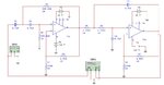
Good Morning, I am struggling to modify a Butterworth filter between 100Hz and 10kHz and unit gain (0dB), I know that to calculate the gain, the formula is G=1+Rf/Ri, the problem is that to achieve 0dB, I need a total gain =1, to have the total gain=0dB (20log(1)), I need 0.5 on each side... how can I add a number to 1 and get 0.5 as answer? Can someone PLEASE help me?
 

Attachments

  • Butterworh.JPG
    Butterworh.JPG
    40.9 KB · Views: 130
Last edited:

I need a total gain =1, to have the total gain=0dB (20log(1)), I need 0.5 on each side...
Are you sure about this calculation? I suggest to multiply gain factors, or add gain in dB. You can decide between 0 dB = 0 dB+ 0 0dB or G = 1 = 1*1
 
i have already tried what you suggested, still not giving the fl 100hz and fh 10kHz at -3db.
 

Total gain = gain1 * gain2, not gain1+ gain2, so you could configure both opamps as unity gain buffers to get unity gain for the whole circuit.

But if you do that it won't be a Butterworth filter anymore unless you change the resistors or capacitors in the feedback network as well.

An easier way is just to put a resistive divider between the two filter sections to reduce the total gain to unity. In the second circuit below, R2 and R9 form the divider. The impedance of the two in parallel is equal to R2 in the original circuit, so the response of the second filter is not changed.

BTW, performance of the circuit will be better if you replace the 741 with something better e.g. TL072.

 
Do you know which values should I use for the capacitors and resistors If I want to keep the circuit as before, without adding the series resistance?
 

As with your previous circuit:
Freq = 1 / (2 * Pi * SQRT(Ra*Rb*Ca*Cb))

When Ra = Rb = R and Ca = Cb = C, that simplifies to:
Freq = 1 / (2 * Pi * R * C) (which is probably what you used before).

Now when gain = unity:
  • For a low pass filter, the feedback capacitor = N * the capacitor to ground.
  • For a high pass filter, the resistor to ground = N * the feedback resistor.
  • For both: N = 4 * Q * Q
    For a Butterworth filter, Q = SQRT(2), so N = 2.

So in this circuit, we need C2 = 2 * C1 and R7 = 2* R8.
(C1 * C2) and (R7 * R8) must stay the same as before though, so we multiply C2 and R7 by SQRT(2), and divide C1 and R8 by SQRT(2).


An easier way is just to put a resistive divider between the two filter sections to reduce the total gain to unity.
Hm. If you don't know to calculate a butterworth filter with G=1, use an equal RC one?

Do you know which values should I use for the capacitors and resistors If I want to keep the circuit as before, without adding the series resistance?
Butterworth low-pass R1 = R2 = R, RC1 = 1.41/omega RC2 0.71/omega
Butterworth high-pass C1 = C2 = C, R1C = 0.71/omega R2C 1.41/omega
 
FilterPro is free download program from Texas Instruments that provides easy active filter design of various orders and types. Saves a lot of grunt calculations.
 
Status
Not open for further replies.

Similar threads

Part and Inventory Search

Welcome to EDABoard.com

Sponsor

Back
Top