Continue to Site

Welcome to EDAboard.com

Welcome to our site! EDAboard.com is an international Electronics Discussion Forum focused on EDA software, circuits, schematics, books, theory, papers, asic, pld, 8051, DSP, Network, RF, Analog Design, PCB, Service Manuals... and a whole lot more! To participate you need to register. Registration is free. Click here to register now.

Active bandpass filter for an audio amplifier heartbeat monitoring device

Status
Not open for further replies.

arnab913

Junior Member level 3
Joined
Jul 27, 2012
Messages
30
Helped
0
Reputation
0
Reaction score
0
Trophy points
1,286
Location
Chittagong, Bangladesh
Activity points
1,515
Hi everyone,
I am working with my project of developing a heartbeat monitoring device. I've built a circuit that gives me output quite well, but there is noise. FIltering it out I wanna design a bandpass filter of range about 60-600 Hz. I've tried in Filterpro designing software, it gave me suggestion to design a 12ordered 6 staged filter circuit!!!:sad:
I am not sure is it possible or not!! It looks too much complicated....but I am not sure.I am uploading the design file.View attachment bandpass_66_600.rar c#.jpg
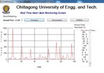
Here is my Output realtime heartbeat and design file.
thanks in advance....
 

Why particularly 12th order? Seriously, how can you conclude this from the shown waveform? By the way, what's the timescale?

12th order is possible of course, but reasonable?
 

The software suggested me 12th order,nothing else. The waveform is plotted realtime on C#. Uc sends data after every 20ms.Baud rate is 9600.
I am also confused is it reasonable or not...
 

On what basis did the software suggest a 12th-order filter? Did you input a desired bandpass frequency and rolloff slope?
 

Uc sends data after every 20ms
Does this mean, the time scale is multiples of 20 ms (2 sec in total)?

What's exactly shown in the "heart beat" axis? It's not an audio sifgnal, may be an envelope or some other derived quantity.
 

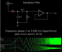
Here is a simple active bandpass filter. It uses 2 capacitors and an op amp. I guess it's a first order.


The capacitor values were adjusted to provide a peak in the approximate frequency range you specified.

Further experimenting would reveal whether your frequency band should go down to 10 Hz, or 1 Hz, etc.
 
Yes.
heartbeat axis actually shows equivalent voltage of heartbeat.
Yes,it is an audio signal,I pulled it down with a 100 k resistor before sampling to thr Uc so that it shows zero level while there is no sound.

- - - Updated - - -

I specified bandpass freq,but there was no option for roll of rate as far as I remember.
 

Status
Not open for further replies.

Similar threads

Part and Inventory Search

Welcome to EDABoard.com

Sponsor

Back
Top