Continue to Site

Welcome to EDAboard.com

Welcome to our site! EDAboard.com is an international Electronics Discussion Forum focused on EDA software, circuits, schematics, books, theory, papers, asic, pld, 8051, DSP, Network, RF, Analog Design, PCB, Service Manuals... and a whole lot more! To participate you need to register. Registration is free. Click here to register now.

active band-pass filter design

Status
Not open for further replies.

lhlbluesky

Banned
Joined
Mar 30, 2007
Messages
558
Helped
5
Reputation
10
Reaction score
5
Trophy points
1,298
Location
china
Activity points
0
i'm a junior for active filter design. i will design a band-pass filter, the input signal is noisy, and my filter must have very good performance of attenuating the noise in both side. the center frequency f0 is 20Khz, Q must be larger than 8, and f0 must be accurate enough(tolerance 2%) for process and temp variation. i was told that, the design is difficult, i have checked some papers, but have no ideas yet, so, pls help me, and tell me what circuit structure should i used? i want it to be 2-order and using one opamp, can this be ok?

besides, i want to ask another question, for active filter (such as twin-t filter), how to decide and calculate the parameter of f0, Q, BW, gain? how to get the formula of them for a complicated transfer function (2-order or high order)? for 2-order filter, i know there is a typical formula just as :
vo/vi=A*w0/Q*s/(s^2+w0/Q*s+w0^2), but for a complicated transfer function or high order (4-order or 5-order) active filter, how to get the formula of f0 and Q? and what is the relationship of these parameters with opamp dc-gain?

if i want to make f0 accurate enough(tolerance 2%) , what methods should i use? and how to do trim for f0 control?

thanks all. pls help me.
 

i'm a junior for active filter design. i will design a band-pass filter, the input signal is noisy, and my filter must have very good performance of attenuating the noise in both side. the center frequency f0 is 20Khz, Q must be larger than 8, and f0 must be accurate enough(tolerance 2%) for process and temp variation. i was told that, the design is difficult, i have checked some papers, but have no ideas yet, so, pls help me, and tell me what circuit structure should i used? i want it to be 2-order and using one opamp, can this be ok?

To question#1: As erikl has proposed, of course, you can use a filter design program. However, I am afraid this does not help you at the present stage of your design activities since you have not selected a particular structure.
Each program offers you several different topologies - that means: You have to decide anyway. After you have made your choice you can and should use such a program for calculating parts values.

Your filter must have "very good performance of noise attenuation". At the same time you specify a pole-Q of at least Q=8 and a 2nd-order transfer function.
The answer is clear: The attenuation for all frequencies far from the center frequency is determined by the order only (1st order slope). The attenuation in the vicinity of fo is determined by the filter Q.
In this context it is important if you have any bandwidth requirement B=fo/Q.

I'll try to give you some hints:
* I do NOT recommend Sallen-Key structures for Q values larger than 5 (for several reasons).
* The multi-feedback topology (twofold-feedback) could probably be used - however, it requires a wide-band opamp (first guess: 10 MHz transit frequency)
* In case you are allowed to use two opamps I recommend the GIC structure (impedance converter principle). This structure enables very good accuracy and easy tuning of the center frequency
without influence on gain and filter Q. It was shown (and published in several articles) that this topology has the best properties regarding active and passive sensitivity.
See here: https://www.google.de/url?sa=t&rct=...pIDACg&usg=AFQjCNGpBTy8Z4WBiXYxe2kVNvQq-svCEg

- - - Updated - - -

besides, i want to ask another question, for active filter (such as twin-t filter), how to decide and calculate the parameter of f0, Q, BW, gain?
.

I suppose this question has no relation to your first question? Because twin-T filters can realize real zeros and, thus, are used for band stop and elliptical filters.
What is the background of this question? For which purpose you need such a filter?
 
Last edited:
  • Like
Reactions: FvM

    FvM

    Points: 2
    Helpful Answer Positive Rating
thanks all.

- - - Updated - - -

as for the question 'besides, i want to ask another question, for active filter (such as twin-t filter), how to decide and calculate the parameter of f0, Q, BW, gain?', i want to know, for a complicated transfer function, how to get the formula of f0 and Q, BW (FH and FL for bandpass), and what is the relationship of f0 and BW and Q? are there some papers to introduce or explain these relationship clearly?
besides, if i want the center frequency to be adjustable off-chip with a resistor or capacitor, what should i do?
and as LvW said, i prepare to use the structure of MFB bandpass filter, and how much gain should i set for the center frequency f0?
thanks all.
 

For a second order bandpass (e.g. a RLC resonant circuit), you can roughly assume BW = f0/Q. Single element tuning of filters is effectively impossible. A a second order filter can be tuned with a single element (some active filters can be R tuned), but with varying Q. The component value variation is corresponding to square of frequency variation.
 

besides, about the noise, i want to filter the noise near 5KHz, 45KHz and 90KHz mainly, and i want the stopband cutoff sharply very much, then, is 2-order design possible for MFB structure? or high-order filter should i use? thanks.
 

besides, about the noise, i want to filter the noise near 5KHz, 45KHz and 90KHz mainly, and i want the stopband cutoff sharply very much, then, is 2-order design possible for MFB structure? or high-order filter should i use? thanks.

This is no specification (sharply very much). From these words I would conclude: Filter order at least 20.
You must specify how much any unwanted component has to be attenuated. This determines the filter order.
 

hi, everyone, thanks for all your reply.
about the noise, i want the noise below 5KHz and above 45KHz as small as possible, may be more than 20dB attenuation, pls give me some advice. should i use high-order fiters?
besides, another question, how to simulate the group delay of bandpass filter in hspice? i want to do the group delay simulation, but don't know how. thanks all.
thanks.
 

You can calculate group delay from phase response. https://en.wikipedia.org/wiki/Group_delay

Fotr the filter, separate low- and high-pass filters are reasonable. The filter order and type selection depnds on the "noise" spectrum, I think. I would start with something normal, e.g. third order butterworth. For interferences at known frequencies near the passband, steeper characteristics or filters with real zeros (Chebychev II or Cauer) can make sense.
 
Last edited:

can anyone give me some schematic or circuit diagram for Chebychev II or Cauer bandpass filter?
and what value for bandpass attenuation (ripple) of bandpass filter should i choose or set? is 1dB OK?
thanks.
 

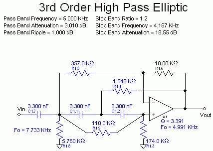
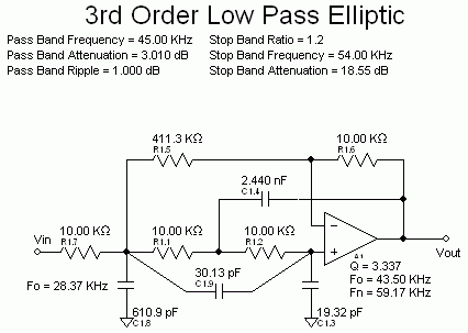
Here's a third order Cauer (elliptic) filter example in Sallen Key topology. Chebychev II uses basically the same circuit topology, with lower Q and no passband ripple. Passband ripple and stopp frequency ratio can be varied.

Nuhertz filter solutions is a good tool to design it.

34_1344960767.gif
 

thanks FvM. i also need some circuit diagram for active bandpas filter of Chebychev II and cauer type, 2-order ior high-order.
besides, can anyone tell me the difference of Chebychev II, Chebychev I, cauer, Butterworth, Bessel? and the difference of Sallen-key, MFB, Fliege and so on?
thanks.
 

besides, what is the difference of a Sallen-key butterworth and a Sallen-key chebyshev active bandpass filter? is it the component selection of R and C? i want a clear explanation, thanks. and i also want some circuit diagrams for chebyshev II type MFB and Sallen-key bandpass filter.
another question, the R and C all have tolerance (1% to 5%), so the center frequency is variable when considering these R and C tolerence, how to avoid the f0 variation caused by R and C tolerence? is there some effective way?
thanks.
 

af-f6.gif
hi, everyone. i have another question here: as i said before, my whole design is a low power design, so the bandpass filter must be low-power also. i have looked at some circuit for MFB BPF, the resistor value may be very high if i make the capacitor is a low value(less than 50pF), then, how to deal with this? besides, what is the expression of center-frequency-gain, center frequency f0 and Q for the MFB active filter as the picture shows? i assume the upper C (10nF) is called C1, upper R (80K) is called R3, while R1 R2 and C2 are also called R1 R2 and C2. what is the exact expression of gain, f0, Q for the MFB circuit?

if i want the (BPF) center frequency is 20KHz, Q larger than 7, C component value is less than 100pF, R component value is less than 1M, then, what circuit should i use for the active BPF design?

thanks all.
 
Last edited:

can anyone tell me the difference of Chebychev II, Chebychev I, cauer, Butterworth, Bessel? and the difference of Sallen-key, MFB, Fliege and so on?
thanks.

1.

The Active Filter Cookbook (by Don Lancaster) covers all or most of these types, and tells how to design a filter to suit desired specs.

It's pretty much a standard reference. Unfortunately it isn't free.

2.

The link below is to an animated simulation, showing Bessel and Butterworth filters, as a simultaneous comparison of the two.

Although they are passive type, not active, it lets you see the better performance of the Bessel, and the action within the capacitors and coils.

Clicking it will open the falstad.com website. Click Allow to start running the Java applet.

https://tinyurl.com/9f4soaf

You can choose from a variety of circuits, including passive and active filters.

You can construct your own circuits. Instructions are on the website.

You can create oscilloscope traces on components. You can create frequency sweeps and observe response.

3.

another question, the R and C all have tolerance (1% to 5%), so the center frequency is variable when considering these R and C tolerence, how to avoid the f0 variation caused by R and C tolerence? is there some effective way?

I once made a biquad filter using 3 op amps, 3 capacitors, etc. I realized that if I wanted high Q, I had to match the capacitor values, and resistors. Time constants had to agree.

I tested many capacitors labelled with the same value, using a simple oscillator. Finally I found 3 that were within 1 percent.

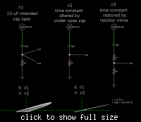
There may have been an easier method to match the capacitors. By adding a resistor inline with the under-spec cap. It increases the time constant (although it also attenuates).

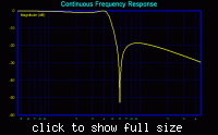
The diagram shows this graphically. The scope trace on the left shows phase change over the range of filter action.

The right-hand scope trace shows phase alignment restored.


This can only be carried so far of course. Installing a resistor has an adverse impact on Q.

So it will depend on which is more crucial, maintaining high Q, or bending a capacitor value a little.
 
Last edited:

thanks FvM. i also need some circuit diagram for active bandpas filter of Chebychev II and cauer type, 2-order ior high-order.
besides, can anyone tell me the difference of Chebychev II, Chebychev I, cauer, Butterworth, Bessel? and the difference of Sallen-key, MFB, Fliege and so on?
thanks.

look at nuhertz's design tools, or at nuhertz's website. They give a lot of good details. the short answer is that some topologies are less sensitive to component variation while others are less sensitive to opamp GBP or opamp output impedance. For example, a sallen-key filter can have equal resistor/capacitor values and control Q by adjusting the gain. The Q changes significantly as gain is varied, and component variations become more important, especially if high Q poles are required. At the same time, sallen-key uses only one opamp for a 2nd order stage.

The filter types have different transition bandwidths, different group delay, and different passband ripple. The chebychev and elliptic filters both have complex zeros, and thus have a stopband ripple spec that isn't based just on the edge of the transition band. Bessel is more common in modern times when used with ADCs that have moderate oversampling ratios. Single order filters are popular with sigma-delta ADCs that oversample by a large amount.
 

Bessel, Butterworth, Chebyshev I have the same transfer function form and circuit topology. They differ by pole/zero position respectively R & C values.

Chebyshev II and Cauer add real zeros to the transfer function which correponds to a complexer circuit.

I presume that the basic third order active filter circuit topology (Sallen Key or MFB) is known from literature. Their design is also supported my free tools like TI Filter Pro.

All filter are sensitive to component tolerances, the more the higher the filter Q. There are also differences between filter topologies.

A band-pass with a larger ratio of corner frequencies should be implemented as a combination of cascaded high- and low-pass filters, as already said.

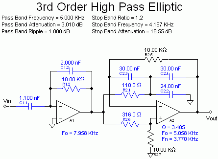
I append example circuits of Cauer high-passes Sallen Key versus MFB.

P.S.: Reviewing other posts, I realized that one point above is given to misunderstanding. With "real zeros" I meaned zeros for real omega values that show as notches in the frequency characteristic. They belong however to pure imaginary s values respectively are placed on the imaginary axis in the pole/zero plot.

88_1345014686.gif


81_1345014784.gif
 
Last edited:
hi, everyone, pls see my reply at 07:17, and answer for me, thanks.
besides, for the filter design, how to decide the opamp parameter(gain, BW, PM, etc) if the filter circuit is already choosen? for ex, if i use the circuit View attachment 78681
, then, how to get the relationship between opamp parameters and R1~R3, c1~C2? or to say, how to make the equalization of feedback loop R and C?
thanks.
 

thanks FvM. i also need some circuit diagram for active bandpas filter of Chebychev II and cauer type, 2-order ior high-order.
besides, can anyone tell me the difference of Chebychev II, Chebychev I, cauer, Butterworth, Bessel? and the difference of Sallen-key, MFB, Fliege and so on?
thanks.

You now have already a lot of information and sources of information.
Realize that filter design is a real trade-off process since you have the choice (after attenuation requirements are fixed) between
*several approximation methods (Butterworth, Bessel, Cheby I and II, Cauer), and
*several circuit topologies.
One can say that all approximations and all topologies have specific advantages and disadvantages.
You can realize all requirements with ALL approximations and/or with ALL topologies - however, the filter order (and with it the amount of amplifiers and passive parts) may be different.
In case of IDEAL conditions (tolerances, opamp) one can say that ALL topologies are exact by 100%.
Differences can be observed only in case of real conditions: parts tolerances, opamp GBW.

You see, it is not possible to answer your question(s) in such a thread. A good book would be the best choice.
However, I would NOT recommend the cookbook from Lancaster.
For my opinion better: Budak, Deliyannis, Ghausi/Laker, Herpy/Berka, Lindquist.
 
  • Like
Reactions: FvM

    FvM

    Points: 2
    Helpful Answer Positive Rating
i have designed a MFB bandpass filter just as the above picture shows. but when i simulate it, i found that, the result is far away from the calculated value. the calculated f0 is 20KHz, Q is 6.5, but the simulation result is f0=16KHz, Q=3.5.
the opamp i use is 5-transistor opamp, gain is 40dB, may be this is a error source; besides, the bandpass filter is followed by a inverting amplifier with Ri=20K and Rf=1M,that is, the following circuit has a gain of -Rf/Ri = -50, the resistive load may be another error source.
when i change the opamp to a ideal VCVS source (gain=10000), the simulation result is Ok (f=19.9KHz, Q=5.5). why? what other reasons can make the bad simulation result?
thanks all, pls help me again.
 

Status
Not open for further replies.

Similar threads

Part and Inventory Search

Welcome to EDABoard.com

Sponsor

Back
Top