Continue to Site

Welcome to EDAboard.com

Welcome to our site! EDAboard.com is an international Electronics Discussion Forum focused on EDA software, circuits, schematics, books, theory, papers, asic, pld, 8051, DSP, Network, RF, Analog Design, PCB, Service Manuals... and a whole lot more! To participate you need to register. Registration is free. Click here to register now.

[SOLVED] Accurately resolving 60Hz phase lag using attached schem

Status
Not open for further replies.

Freddybaby

Member level 4
Joined
Sep 27, 2007
Messages
70
Helped
3
Reputation
6
Reaction score
1
Trophy points
1,288
Location
California, USA
Activity points
1,816
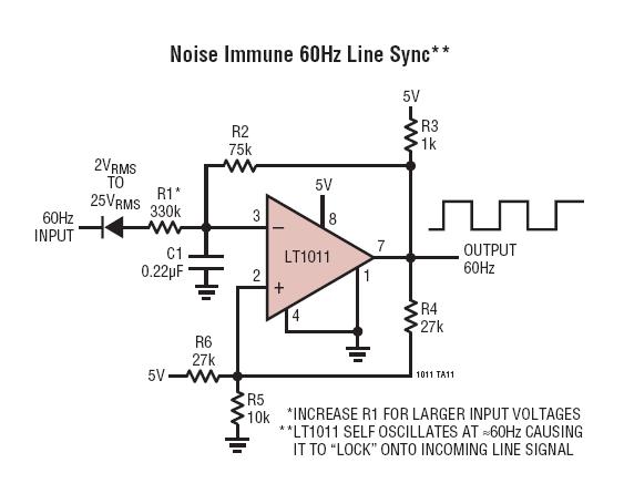
Thinking of using this method to determine phase lag between 2 60Hz sources. I need resolution and decent accuracy to about 8 minutes (0.13 degrees).

My questions are;

Will the crosstalk between amps introduce errors. ?

Do I need to match the forward drops of the input diodes (or use matched sets such as LM394 configured as diode) ?

Can I use input offset correction to trim the delays between ?


I would highly recommend that you NOT use that circuit. As far as I can tell, it is a injection-locked self oscillating system. Frequency locked systems are NOT phase locked, and you will have a big input to output phase error, and it will be temperature and power supply dependent!

Since you are at 60 Hz, I would just use two DC crossing detectors (high speed comparators), and drive a set/reset type counter, that counts a higher frequency signal. Something like a stable 1 MHz signal, gated on/off with the two zero crossings. Your count is proporitonal to the difference between the two inputs.

You could use a cheaper circuit, like a ramping signal on a capacitor started by one zero crossing, and a sample and hold sampling the voltage of the capacitor at the other zero crossing. Voltage sampled is propostional to phase difference between the two inputs. You need to drive the capacitor with a current source to get a linear ramp.

Rich
 
Last edited by a moderator:
Thanks for the input.. I had my suspicion that this might be unstable given it is a "self oscillating" config... I don't even need to go into a counter, this will drive my scope to determine the matching of a passive phase correction network. So a basic "off the shelf" zero detector will probably work better.. I just hope I can get them matched with a common input and that it won't drift too far...

Thanks again for saving me the prototype time biff44
 

I counted your needs in that circuit

If voltage peak2peak is 24V then voltage 0.13 degr. >> 54.45mV
time for 0.13degr. >> 6.02 microsec.

so we can see ,that higher voltage gives bigger input signal ( easier adjustment )

I think if you can use highest possible input voltage and use clipping circuit
as zero cross detector , it is possible to make thatkind of detector quit easy.

Do you need information at direction of phase difference. ( which pulse came first)
and what is the maximum difference value this circuit should handle.

Can you tell me what is the voltage you detect ( 110V 240V or ?? )

I think about that circuit ( clock is now in finland 00.50 ) i will come back tomorrow.

Regards KAK
 
Last edited:

The application is for accurate phase display on a scope. My detection range is different between the two input signals as I'm evaluating
compensated voltage dividers for power metering applications. As much as a 1000:1 difference. I have looked at several designs and am
trying to decide what approach. The clipping diode method may work but I will have to put a divider in front of one "channel" and be able to
vary the delay to sync the 2 inputs.
 

I was also wondering if a change of slope detector might be more suitable than zero crossing ? I have never seen anyone use this method for phase detection
and have never worked with this type of circuit. Anyone have any comments on this ?
 

Status
Not open for further replies.

Part and Inventory Search

Welcome to EDABoard.com

Sponsor

Back
Top