Continue to Site

Welcome to EDAboard.com

Welcome to our site! EDAboard.com is an international Electronics Discussion Forum focused on EDA software, circuits, schematics, books, theory, papers, asic, pld, 8051, DSP, Network, RF, Analog Design, PCB, Service Manuals... and a whole lot more! To participate you need to register. Registration is free. Click here to register now.

[SOLVED] Accurate Voltage Measurement with Arduino

Status
Not open for further replies.

element

Newbie level 5
Joined
May 14, 2015
Messages
8
Helped
0
Reputation
0
Reaction score
0
Trophy points
1
Location
Karachi
Activity points
86
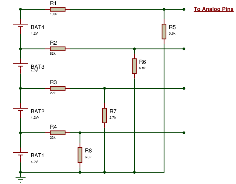
I need to monitor voltages of Li-Ion cells stacked in series and appropriately operate protection circuitry using Arduino.

1. First I ran into the problem of using <10kOhm resistors for a voltage divider as per the ATmega328 datasheet because when I tried to use large value resistors the readings were jumping a lot even though I took mode of 5 analog readings in the software...

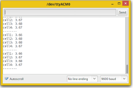
2. Then there is this problem of fluctuating Vcc of the arduino which is used as Vref for analog measurements...So, I decided to switch to the internal 1.1V which actually turned out to be 1.085V for my board....this gave nice results when I measured across each ResistorDivider separately...but when I try to measure the voltages of all the cells in series at the same time and subtracting them in the software to get each cell's voltage...1st two cell voltages were fine...but the third was always problematic...i tried to change the Arduino board..double checked all connections...but still it gave abnormal readings....although the same resistor divider when checked separately was working correctly for 3 cells....

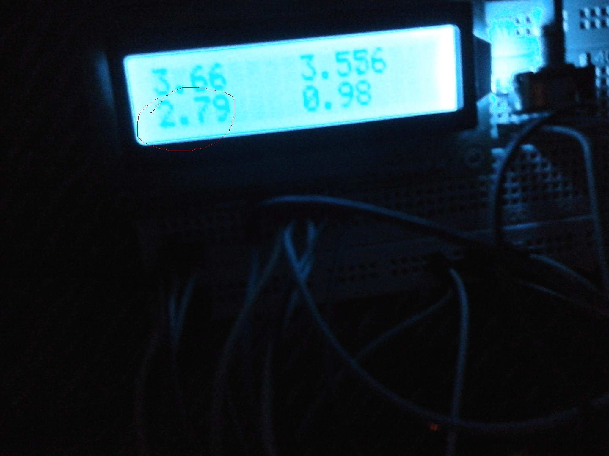
3. I decided to use a difference amplifier...used an LM324N opamp and made a difference amplifier...but the problem is even though I connected 0-9V at its across its rails..and tried to measure a cell that has voltage of 3.66V...the output pin of the 324N gave 3.33V.....so I thought maybe it gives an output of (3.66-3.33)= 0.33V....but for the other cell this subtraction factor changed....

SOOO... what should I do.. should I use precision resistors or some Precision Difference Amp like INA154 or INA133 (would they give accurate output voltages when I have enough supply on the rails)??

I am stuck with this voltage measurement problem! :-x

PS: I tried to use the AREF pin and supplied it through LM7805..but when I connect the Output of 7805 to the AREF pin...the voltage drops from 4.99 to some 3.XX....now what's that? I am really a noob at electronics..don't know much
 

Hi,

For a LiIon voltage measurement you need:
* a voltage measurement with good (<1% error) absolute accuracy
* not big analog bandwidth (<10 Hz)
* not high sampling rate (<20 smpls/s)

To 1)
For good accuracy i recommend a differential measurement with internal reference (instead of vcc as ref)
I don't really remember, but is the only selectable internal voltage reference 1.1V? Isn't there a 2.5V one?
Then you need a voltage divider for each cell joint, and the upper and lower end.
It depends on total battery voltage. But since you don't need high sampling rate you could use a high ohmic voltage divider combined with a capacitor as low pass filter. When you have 4 cells you need 5 voltage dividers.
Try 200k, 10k and a 1uF capacitor in parallel to 10k. Connenct the capacitor next to the ADC with short wide traces to AGND a nd the ADC input. This gives a nominal input range of 0...23.1V. I don't know if this fits your application, adjust it. With a 10 bit ADC you will get a resolution of about 23mV per Lsb. This should be sufficient even when measuring a single cell.
Add a capacitor for Vref to the according pin and AGND.
Choose a fixed defined sampling rate using timers and interrupts.
100 samples per second should be enough. Multiplexing the channels..

* The higher the sampling rate the worse the accuracy, because of the capacitive effect of the sample and hold capacitor of the SAR ADC.
* Maybe Vref is really 1.085V. But it should not significantely change with time and temperature. To compensate the error a simple multiplication fir calibration in software should work. No big challenge. If you don't want to a independent calibration you need a higher accuracy external Vref. Use a 2.5V one or a 3.0V one, adjust the voltage divider for input range.

Please -especially with high ohmic voltage divider - don't use ADC sample control in main loop with unequal timing, this gives jumps in voltage readings.

With fixed ADC timing you could use a simple digital low pass filter for each ADC channel. This could improve voltage readings when you encounter noisy readings. But with the given setup there should be stable readings down to +/- 1 LSB. Within the ADC isr you should store the independent channel values in independent variables, so that you always and continously have reliable data available in the main loop. Mind "atomic" access to the data in main loop.
Processing the data in main loop should also be done sychronously to sampling rate, but this is not that important...

So far so good. Try this and tell us your experience.
For further discussion a simple schematic of your configuration would help. Also important values like cell count and cell voltage and so on...

I don't think you need OPAMPs.

Btw. All the wires from battery to voltage divider must not carry power current. Therfore you need independent lines for power and voltage sense.

Good luck

Klaus
 

* I am using an Arduino Uno, it has a 1.1V internal ref available, the other one is Mega2560 with 2.56V internal ref

* Actually, I am working on developing a 7S2P Li-Ion pack...I have attached a simple schematic of only the voltage measurement ckt...I will be using the Arduino Mega in the final design as it has 16 ADC channels.

* I am assuming that by using a capacitor the readings will become stable...but the readings are already stable..they don't fluctuate

* I will try to reduce the sampling rate...by default with a prescaler of 128 ..... 16Mhz/128=125kHz...since a single conversion takes 13 ADC cycles, the sampling rate is 125kHz/13= ~9600Hz....but if I use timer interrupts to reduce sampling rate I wont be able to use delay() function in the program...anyways for checking purposes

* I have attached a picture of the output on LCD where you can see, the 3rd cell in the [2ndrow,1stcolumn] is giving abnormal readings which is also disturbing cell4 as I am using differential voltage measurement..and nothing is wrong with the connections or the cell..whether I use 5V or 1.1V as ref...this problem persists!


Sorry, I attached the old serial output...anyways...this is the output with the problematic cell3 at the bottom left


Hi,

I recommend to us the same value voltage dividers on all channels. (Maybe 10k to Gnd and 300k ...350k to thecells)
And i strongly recommend to use capacitors at each ADC input. At least 100nF, better 1uF X7R ceramics with at least 16V, better 25V or 50V voltage rating

As said before: use an additional voltage divider and ADC channel for battery low side sense.

Each channel circuit should be equal for best results.

(I know you think choosing independent voltage dividers improve voltage reading. It improves resolution with the lower voltages, but the higher voltages are worse.
Every resistor of the same value should be from the same production batch to have about the same absolute error and about the same drifts.)
7 × 4.2V = 29.4V. With an accurate ADC reading you get a resolution (at each channel) of about 30mV this should be OK.

If you need better resolution, then use two 8 to 1 MUX and an external difference amplifier for reading each cell independently.

Mind: better resolution does not mean better accuracy.

Klaus
 

Hi Kluas,

It is finally working... I used INA105 (precision difference amps) with a unity gain and got results accurate upto 2 significant digits after the decimal place....I also added a mux and a demux to increase the i/o pins of the atmega328p...and now it is time to design the PCB. Thanks for suggesting a mux...I almost forgot how useful it would prove in this design...When I complete this project ....will definitely show you
 

Status
Not open for further replies.

Similar threads

Part and Inventory Search

Welcome to EDABoard.com

Sponsor

Back
Top