Vermes
Advanced Member level 4
Assumptions:
- smooth regulation of charge current (adjustable PWM approximately 20Hz)
- cutting off the charging when set voltage exceeded
- after the charging is cut off, reloading after previous reduction below a set threshold (desulfurization mode)
- operation in temperature range from -10 to +30 degrees Celsius
- lack of forced air flow
- resistance to rain
- adapted to 6V and 12V accumulators
- no microprocessors/displays
- low cost
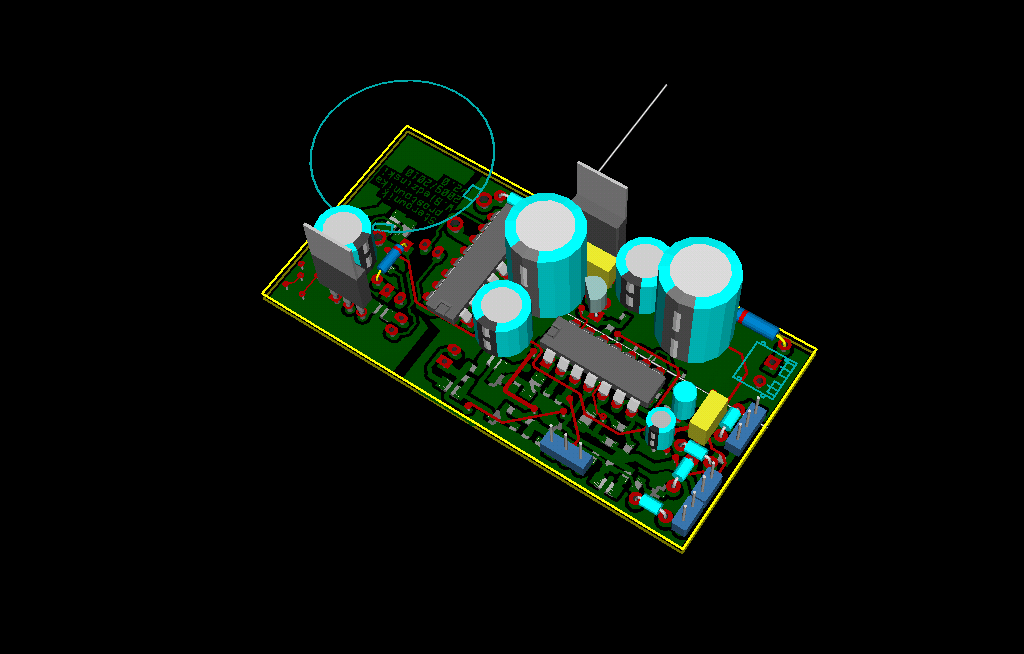
- design in KiCAD
- charging current min 4A
Design:
Assumptions were met in the second version of SCH and PCB, the first version had no PWM current regulation.
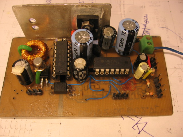
Implementation:
Transistor has heat sink, because the following elements heat up:
- rectifying diodes
- ammeter shunt
- 7812 stabilizer
- transformer

Principle of operation:
- PWM regulator – there is a triangular signal at the generator output and it is compared to the potentiometer voltage on the comparator. In that way you get a rectangle with adjustable filling.
- voltage measurement system – the reference voltage source is TL431, it is compared to the accumulator current voltage on the comparator (with hysteresis)
- executing system – N mosfer transistor – controlled by galvanic isolated inferface – cuts off „+” to the accumulator
Behavior of the system – the algorithm of operation:
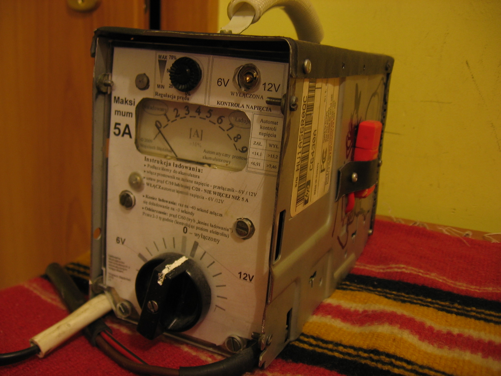
- after turning on a discharged accumulator, the rectifier loads like any other, except that you can set the average current (average because the PWM 20Hz is visible on the ammeter – you can see the hand vibrations)
- when the accumulator is loaded and threshold 15,2V is exceeded – the system cuts off the charging
- then the behavior of the system depends on the accumulator state: the system waits until the voltage on clamps drops below approximately 14V. In fully efficient accumulators after fully charging the voltage from drops quite slowly from 15V – even for a minute. In a sulphated accumulator, voltage on terminals drops very quickly – within a few-dozen seconds
- when the voltage drops below 14V, the system again switches the charging and when the system loads itself >15,2V, it turns off again. Such subsequent charging takes a few seconds, depending on the set charging current
- „loading”/”pause” cycles are repeated until the rectifier is turned off. The charged and/or accumulator state can be judged by estimating the ratio of „loading”/”pause” time. Such cycles cause a few seconds recharging the accumulators every few tens seconds
- pulse current (PWM) and a slight gassing of the accumulator: it is to stimulate the crystals to dissolve
Link to original thread (useful attachment) – Prostownik akumulatorowy z regulacją prądu