Scolioza
Member level 1

- Joined
- Mar 5, 2013
- Messages
- 34
- Helped
- 0
- Reputation
- 0
- Reaction score
- 0
- Trophy points
- 1,286
- Activity points
- 1,561
Hi all.
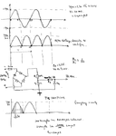
I want to design an AC (230V 50Hz) voltage monitor using PIC 16f886 uc. I read a lot of topics about this problem and i want to ask here some questions. Because one picture worths more than 1000 words i will attach a picture with my calculations:

1. It is ok to use the circuit in the picture? I know that there is no insulation. If i will use a transformer how it will affect the precision?
2.Using a 20Mhz crystal osc. will result 1 instruction in 0.2us. Using Frc for adc will result ~6us/bit. TAD=6X11=66 us. I dont understad if Tacq is the value for 1 bit (it will multiply by 11) or for the entire convertion.
3. Assuming that Tacq is the value for one bit (worst case) and it is ~4us and ts is 200us (according to picture) between two sampling will remain 200-(6x11+4*11)=90us for instructions. Hence 1 instruction is executed in 0.2us will result 450 instruction to execute before taking the next sample. The RMS voltage is :
√((V1²+V2²+...+V100²)/100).
I am not good in assambler so i am using mikroC. Suppose that i am using the following algorithm:
a) generate a timer1 interrupt every 200us
b)after adc will reamain 450 instructions to execute before the next interrupt
Is there enough time to convert digital value back in analog domain, raise to the power of two and add to the previous value?
Thanks in advance!
I want to design an AC (230V 50Hz) voltage monitor using PIC 16f886 uc. I read a lot of topics about this problem and i want to ask here some questions. Because one picture worths more than 1000 words i will attach a picture with my calculations:

1. It is ok to use the circuit in the picture? I know that there is no insulation. If i will use a transformer how it will affect the precision?
2.Using a 20Mhz crystal osc. will result 1 instruction in 0.2us. Using Frc for adc will result ~6us/bit. TAD=6X11=66 us. I dont understad if Tacq is the value for 1 bit (it will multiply by 11) or for the entire convertion.
3. Assuming that Tacq is the value for one bit (worst case) and it is ~4us and ts is 200us (according to picture) between two sampling will remain 200-(6x11+4*11)=90us for instructions. Hence 1 instruction is executed in 0.2us will result 450 instruction to execute before taking the next sample. The RMS voltage is :
√((V1²+V2²+...+V100²)/100).
I am not good in assambler so i am using mikroC. Suppose that i am using the following algorithm:
a) generate a timer1 interrupt every 200us
b)after adc will reamain 450 instructions to execute before the next interrupt
Is there enough time to convert digital value back in analog domain, raise to the power of two and add to the previous value?
Thanks in advance!


