Continue to Site

Welcome to EDAboard.com

Welcome to our site! EDAboard.com is an international Electronics Discussion Forum focused on EDA software, circuits, schematics, books, theory, papers, asic, pld, 8051, DSP, Network, RF, Analog Design, PCB, Service Manuals... and a whole lot more! To participate you need to register. Registration is free. Click here to register now.

AC to DC Matrix converter Driver circuit Design

Status
Not open for further replies.

adnan012

Advanced Member level 1
Joined
Oct 6, 2006
Messages
468
Helped
2
Reputation
4
Reaction score
2
Trophy points
1,298
Activity points
4,923
hi,

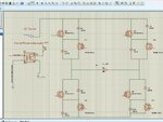
I want to design the matrix converter given in the attached file. There is an AC source connected to the bidirectional switches. How gates are derived in this situation? I have generated required signal patterns using pic controller and each signal is isolated via opto coupler. I don't know how to interface the output side of the opto couple to the matrix converter switches gates? Do i need to use mosfet driver like irs2110 for driving high side and low side switches?
 

Attachments

  • A High Power Factor Matr ix AC to DC Converter Using Atmega 32 as the Signal Generator.pdf
    122.4 KB · Views: 67
  • Slide1.JPG
    Slide1.JPG
    152.5 KB · Views: 64

I don't think that IR2110 can work for this circuit topology. You need an isoated power supply for each switch branch.
 
Thanks for reply.

Can you explain in more detail?

- - - Updated - - -

The switch network is connected to a step down 12 volt transformer.

- - - Updated - - -

The controller board is powered by the rectified output of another step down 12 volt transformer (using bridge and 5v regulator).

- - - Updated - - -

How can i realize an isoated power supply for each switch branch? there are 4 opto couplers, do i need to power them with different isolated power supplied?
 

I have found a document related to the issue. At page 289 figure 12, there are four boards.

1) Controller Board (upper left )
2) Voltage regulator Board (Bottom left)
3) Opto coupler board (Bottom Right)
4) Coverter Board (upper Right)

There are 5 transformers.
 

Attachments

  • Single-Phase Z-source Matrix Converter with High Voltage Gain.pdf
    269 KB · Views: 51

Status
Not open for further replies.

Similar threads

Part and Inventory Search

Welcome to EDABoard.com

Sponsor

Back
Top