Continue to Site

Welcome to EDAboard.com

Welcome to our site! EDAboard.com is an international Electronics Discussion Forum focused on EDA software, circuits, schematics, books, theory, papers, asic, pld, 8051, DSP, Network, RF, Analog Design, PCB, Service Manuals... and a whole lot more! To participate you need to register. Registration is free. Click here to register now.

AC to AC converter

Status
Not open for further replies.

santoshtambe76@yahoo.com

Newbie level 4
Joined
Sep 3, 2012
Messages
7
Helped
0
Reputation
0
Reaction score
0
Trophy points
1,281
Activity points
1,357
Hello All

I want design AC ( universal input 90Vac to 230Vac) to AC converter of 5000Vrms sine shape, 500Khz frequency and 500Watt power.
Can anyone suggest , how to design/topology for it ?
 

Simplest approach is, UPF booster to 400V

then a sine shaped full bridge with several transformers ( outputs in series ) to get the 5kV 500kHz

beware though, as this voltage and freq will track very easily across even a slightly contaminated pcb ( finger print, breath, moisture, humidity ) etc ....

make sure you have an effective current / power limit.
 

The ARRL handbook comes out every year, and every year most of it carries over from previous years. ANY issue will have all the design information required to design a 500+ watt tube radio transmitter.
Older issues should be available fairly cheaply from Amazon etc and be just as useful as the current version.

Many PWM chips run at 500 Khz these days and would provide a suitable duty cycle controlled drive signal.
It should provide a pretty robust and trouble free 5Kv adjustable output voltage RF supply without too many problewms.

Cheers, VK3ALY.
 

The newer handbooks and articles focus a lot on LDMOS LV stuff, so OP specs
steer one to Vacuum Tube. In the old handbooks are various config-
urations for modulation and architecture, so do not dismiss the older
handbooks.

Regards, Dana.
 

I have been out of it for a long time, my copy is 2003. Just reading through it now in fact and its all there.

If the original poster is still around, I can scan relevant pages if required.
Original poster may prefer semiconductors, but there will be huge problems winding transformers with 5Kv insulation that will operate at 500 Khz.

Much easier to get 2.5 to 3Kv dc from a mains frequency transformer/rectifier and drive an air cored tank coil with a tube.
After all, microwave ovens do something vaguely similar and that works fine.
 

How about an old fashioned vacuum tube driving a tuned tank circuit ?
please name a tube that can do 500W continuously that isn't WAY more expensive than the silicon alternative - then there are the shipping and handling issues and then the fact the tube simply will not last very long at that power - even setting cathode heating issues aside - these are only some of the reasons tubes are not used in industry very much at all these days - also a useful tube ckt would have to be a push-pull - which leads us back to transformer design - which is where all the engineering effort is required for this project ....
 

Sorry, I did not know cost was to be a criteria in this discussion.

Tubes are used all over the place in industry. Commercial radio transmitters, induction heaters, every microwave oven has a magnetron in it. With proper design, tubes can last for years. I have Tektronix oscilloscopes here that use a cathode ray tube that must be forty years old and it still works perfectly well.

I would love to see a microwave oven driven by silicon, I really would !

Anyhow there are only two practical ways to generate a 5Kv sine wave, either a resonant tank, or with a step up transformer. The problem with a transformer is getting enough turns and inductance to generate 5Kv while keeping the capacitance low enough. The whole thing must have a self resonance far enough above the operating frequency, or its no longer inductive. There are plenty of tricks, but honestly 5Kv and 500Khz, its just not realistic. It would be very difficult to do 5Kv at 50Khz.

The only reason a Tesla coil works as well as it does is because its resonant. And a resonant tank circuit is the way to go here too. That can certainly be done with semiconductors, no argument there, its just a lot simpler with a tube. And it certainly does not need to be push pull drive if its resonant.
--- Updated ---

which leads us back to transformer design - which is where all the engineering effort is required for this project ....
Definitely agree.

Its not wimply little pulses either, its 500 solid RMS watts.
Skin effect and capacitance are very significant problems at that frequency.

Its way beyond me I am afraid, but I am eagerly awaiting to hear how you would go about it with a suggested transformer design.
 
Last edited:

cost is always a consideration - I could not see the tubes recommended by you, we do 1kV at 2.6MHz, with silicon, 5kV at 0.5MHz would be doable if method mentioned was followed, post#4.
--- Updated ---

p,s. CRT's are a special case, designed for longevity, and do not run at 500 watts - considerations you appear to have over looked.
 

Hi,
5000Vrms -> 7070Vdc peak
500kHz - > 1us for voltage rise from 0V to 7070V peak
Slew rate apply to linear switch = 7070V/1us, this is very high for apply directly to one silicon.
I have Three solutions:
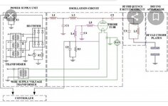
1 - Simplest: use vacuum tube as other member said. This solution can change frequency by change value of LC in resonant tank. (the attach picture is copy from Internet/ Google). The most expensive and low efficciency.
2 - Basic: 220Vac -> 400Vdc PFC -> Full bridge vs Mosfet, f0 <= 500kHz LC resonant tank, transformer with ratio: >7070V:400V -> (option: <= 500kHz LC resonant tank filter )-> Output: 5000Vac - 500kHz. This solution can adjust frequency but the gain of voltage will change follow frequency so need design higher transformer voltage ratio. The most advantage of this solution is isolation power from 220Vac grid to output.
3- Adventure: 220Vac ->adjustable 400V-800Vdc PFC -> Full bridge/Halbrige vs Mosfet + < 500kHz LC resonant tank. Output is 02 pin of L or C in resonant tank. When operate close to resonant point, voltage swing on L & C component is very high. So, to stable output Vpp and Power, we need adjust Vdc supply and reduce more resonant frequency of tank < 500Khz. This solution has no isolation fron 220Vac Grid, controller & protection is complex. But is lowest cost solution and high efficiency with ZVS mode. This is like LLC converter or Induction cooker/heater. Because of high dV/dt make high radiated EMI noise , should take care shield, isolation for controller/ system working properly.
 

Attachments

  • amp tube.jpg
    amp tube.jpg
    278.9 KB · Views: 81

Hi,

5000Vrms -> 7070Vdc peak
500kHz - > 1us for voltage rise from 0V to 7070V peak

a 5000V RMS sine has +/- 7070 V peak.
it goes from 0V --> +7070V --> 0V --> -7070V --> 0V ...all this in 2us (4 x 0.5us)
so from 0V to 7070V in 0.5us (14140V/us)

but a sinewave has no liner rise rate.
maximum rise rate (is at zero cross) is: Pi x V_RMS * sqrt(2) / 2us = 22214 V/us

Klaus
 
I got 22,214.4 too V / uS ( converted all to radians )

still a fairly high rate of rise at the zero crossing, in a 1pF capacitor this is 22.2mA, 2.22 amps in an 100pF.
 

Which is one of the factors which makes winding a conventional voltage step up transformer extremely difficult and not really a practical proposition.

On the other hand, a resonant tank circuit can generate a very high power low distortion sine wave at high voltage, and the power fed into it can be in the form of rectangular pulses of adjustable duty cycle to control the final amplitude with voltage feedback.

Driver could be a tube or mosfets.
 

a resonant tank consists of an L and a C, all the problems you associate with a Tx apply to the L equally,

hence post #4
 

Its a totally different situation. The magic of resonance changes everything.

You need a far lower coupling coefficient to get energy into and out of a perfectly resonant circuit.
That evil shunt capacitance effectively disappears when Xl = Xc.
 
Last edited:

aah, you reveal a lack of understanding, respectfully, the L & C are still there at resonance and the resonant current sloshes back and forward between the two, if the C is part of the L and the Q is high, these currents can be quite large ( I internal = Q x I external )

for the frequency and voltage in this thread - a high knowledge of low loss, low C wdg is required, else the capacitive currents will overwhelm the driver ....
 

Yes you are quite right, resonant Q must be carefully chosen. Too low, and the benefits of resonance are not achieved, too high and as you say, circulating currents can burn up your inductor. The optimum design Q in the world of resonant transmitter tank circuits is usually about seven. That provides sufficient Q for harmonic attenuation and in practice works just fine.

So our load current will be 100mA and our optimum circulating current about 700mA a quite manegable figure.
Xc will of course be one seventh of the load or 7.14K Xl will also be 7.14K ohms, so that determines the values in our tank circuit. So we need about 2.27mH plus 44.6pF for our tank.

That is quite easy with a large air cored coil and an air spaced tuning capacitor.

It would be rather difficult to wind a ferrite cored transformer that had at least 2.27mH with less than 44pF total capacitance that will couple 500 watts.

I can tell you how to build an air cored tank coil that will carry 700mA with 2.27mH and easily have the required voltage insulation and low capacitance.

Now I want YOU to tell me how you plan to wind a ferrite cored transformer that meets all the requirements.
I want to know the core, wire sizes, and winding layout.
No good saying easy, I want you to present an actual design proposal for this.
 

Status
Not open for further replies.

Similar threads

Part and Inventory Search

Welcome to EDABoard.com

Sponsor

Back
Top