Continue to Site

Welcome to EDAboard.com

Welcome to our site! EDAboard.com is an international Electronics Discussion Forum focused on EDA software, circuits, schematics, books, theory, papers, asic, pld, 8051, DSP, Network, RF, Analog Design, PCB, Service Manuals... and a whole lot more! To participate you need to register. Registration is free. Click here to register now.

AC to AC converter

Status
Not open for further replies.

santoshtambe76@yahoo.com

Newbie level 4
Joined
Sep 3, 2012
Messages
7
Helped
0
Reputation
0
Reaction score
0
Trophy points
1,281
Activity points
1,357
Hello All

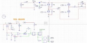
I want design AC ( universal input 90Vac to 230Vac) to AC converter of 5000Vrms sine shape, 500Khz frequency and 500Watt power.
Can anyone suggest , how to design/topology for it ?
 

I don't think our clients would be too happy disclosing our techniques for high power, high freq, high voltage transformers - but post #4 gives a clue

As to Q - it is a funny thing - that requires a high degree of understanding - if a choke has a high Q at a high frequency, then it must by definition have a low Rac and low core losses ( and low capacitive dielectric losses for any C it contains ) - this allows significant resonant current to flow with lower loss than for lower Q rated parts - which would indeed get hot for the same current.

700mA is 3.5kVA in the LC circuit for a Q of seven the external power required will be 500 watts - and this will all be dissipated in the L & C if they truly have a combined Q of only 7.

Better to have a much higher Q and have the load soak up the 500W

or direct drive a transformer as can be done without too much fuss and without the issue of resonance induced amplitude change when things warm up in the LC circuit - as they must - necessitating some form of frequency control - to control the amplitude - i.e. a fixed 500kHz may not be able to obtained at 5kV ac exactly ... without extra control.
 

So its a secret ! Hahaha.

Yes it will be relartively lossy, rather large too, but its mainly about safe temperature rise.
That starts with skin effect and wire size. As a tank coil will be single layer and fully exposed, we can run a fairly high current density without it bursting into flames. Skin depth at 500 Khz is roughly .093mm and if we use 0.5mm wire we will be using about 60% of the wire cross section. O.5mm wire will get warm at 700mA but not excessively so.

Using Wheelers Formula, and choosing reasonable coil proportions, a coil of 75mm diameter, 125mm long with 250 turns should be about 2.2mH. The exact inductance is not critical if we use a variable capacitor.

If the massive EM radiation from such an open coil worries you, an alternative solution would be a powdered iron toroid. Magnetics make a 5.2 inch toroid in type 2 material that would work with about 330 turns. Al is 20nH/turn. That would get only slightly warm at 127mT with 5Kv. Although I do worry about the insulation.

All good well time proven engineering. And funnily enough I have all the exact right parts here to put together such a beast right now if I wanted to. Have the tube QB3.5 750, have the Magnetics T520-2 (red) core, have a suitable tuning capacitor and dc supply as well.
The data book says the QB3.3-750 is good for 800 watts rms at 2.5Kv dc. That should do.

A practical solution for the original poster that I am willing to share, not top secret mystical pie in the sky secret B.S. which is of no help to anyone.
2021-11-01_0001.jpg

--- Updated ---

Amplitude control will be vital, whatever the method of generating the 5Kv at such high impedance.
No need to control the frequency. Just use a standard PWM switching power supply chip set to run at 500 Khz, and use voltage feedback to control the duty cycle driving the resonant tank, for a fully regulated output voltage.

Very simple, no mystery.
 
Last edited:

- if you are relying on a resonant step up the power circuit will be very touchy ( high gain ) around the pwm point that gives 5000Vac, this is why direct drive is often preferred ....
--- Updated ---

also - loading a parallel LC ckt lowers its natural res freq, fo, the C associated with 250 turns may well mean you'll never get as high as 500kHz.
 

All valid points.
Voltage feedback should cover the high output voltage sensitivity, and simple first order compensation should react very quickly and be completely stable.

The tank values specified should work fine for a resistive load.
If its fitted with an output tuning capacitor as recommended, it will allow for some additional stray load capacitance, but not a lot. If the load is reactive, resonance should still be achievable, but with different tank component values.

That could also be a potential problem with an ordinary untuned transformer output, especially if the load becomes predominantly capacitive. That would be reflected directly back into the primary possibly causing some issues with semiconductor current.

Your approach is definitely better if it can be done, but doing it the old fashioned way should have far fewer unexpected problems and be a lot easier for most people to get going first attempt.
 

Unfortunately 2.2mH for the L implies 46pF for the C, the wdg C will almost certainly be larger than this for 330 turns as suggested in post #22

thus 500kHz will not be able to be reached - the capacitance attached to either end of the L must be considered also - if it forms any sort of closed loop ckt.
 

Hi man
As my experiment design and tested with Induction cooker, its principle is same with using "open/un-fixed" LC resonant tank (resonant point can change by load).
The key of circuit is phase dectection, to protect IGBT/Mosfet out of spoild when operate in hard switching mode.
When switching frequency (Fsw) close resonant point (F0), I have to check phase of current and voltage allply to coil - Inductor is still lagging or leading.
Fsw > F0, IGBT/Mosfet get ZVS and low lost (very cool). The most lost power drop on Inductor because high current and high frequency (wire lost & core lost).
With 220Vac, Fsw = 0.9 F0, the total lost power without pot in plate is 250W (10% of max power 2500W with pot in, coil used of 1800W type instead of 3000W's -> over design/ working point).
With my first prototype don't have phase protection, IGBT/Mosfet is spoilded when pot remove or place in. Now is no problem.
LC component will define a resosant point, but this point is not fix at all. It is efffected by load, by frequency, by temperature, by dc apply voltage.
So, to working properly should have phase detection to reduce switching lost and get maximum gain at resonant point when shift control frequency.
Beside phase detect, it is sure to sense & protect peak current through coild, peak voltage apply to capacitor to ensure all condition in control.
For 500kHz is quite high frequency need strong driver IC for Mosfet, isolate control signal is prefer if using MCU.
Because of higher switching frequency should optimize these:
- Use fast switching body diode mosfet -> reduce spike on mosfet.
- Use damper to reduce ringing when on/off mosfet and get ZVS
- Correct deadtime long enough -> reduce spike on mosfet.
- Strong driver place close mosfet to reduce effect of noise.
If not optimize, my MCU was isolated from power stage still reset after increase power.
When measure by oscilloscope, can see many spike with current and voltage line.
After, it is smooth shape.
 

Attachments

  • ind cooker.JPG
    ind cooker.JPG
    89.5 KB · Views: 68

Unfortunately 2.2mH for the L implies 46pF for the C, the wdg C will almost certainly be larger than this for 330 turns as suggested in post #22

thus 500kHz will not be able to be reached - the capacitance attached to either end of the L must be considered also - if it forms any sort of closed loop ckt.
Not true.
The inductance can be tapped at any point, likewise the capacitance can be tapped, which is the more usual way of matching the tube impedance (about 4.5K here) to the load impedance and produce some low pass harmonic filtering for free. Clearly you are not a radio frequency guy.
Pi couplers are ubiquitous for impedance matching in the radio world.

A long single layer air cored coil will have negligible capacitance end to end. Similar tube circuits can be tuned to at least 100+ Mhz very easily in radio transmitters without any difficulty at all.

A single layer wound on a toroid will certainly have some capacitance down to the core, but the effect of that depends on the resistivity of the core material at the operating frequency. Very low loss material such as the -2 powdered iron material should not have much more effect than air on capacitance.
Resistivity is pretty much tied to eddy current loss, and extremely high resistivity negates capacitance.
For several reasons powdered iron is more preferable than ferrite at radio frequencies.

But I agree that the much higher permeability low frequency ferrites for example, do have this problem of capacitance down to the core.

Distributed capacitance is a much bigger problem with multiturn layers, and layering turns only really becomes necessary in a transformer where the whole thing must fit within a magnetic core of some type..

Taihung, yes quite right.
Often the load reactance/impedance can be rather uncertain as for example induction heating, and driving ultrasonic transducers. Phase detection, or making the reactive load part of an oscillator circuit ensures resonant operation, even if the operating frequency moves around. Many other ways to do this too with phased locked loops for example.
 
Last edited:

There are no tube circuits with 2.2mH inductors in the power signal train operating at 500kHz

yes you can tap the inductor - but the wdg capacitance - end to end - remains - you suggested the iron powder toroid as a suitable core - unless my eye sight is off - it is not a long solenoid air cored core - is it ? how long would it have to be to get 2.2mH ? much longer than a metre - so impractical right off the bat.

So - using your suggested core - we cannot get down to 46pF end to end - even with your magical tapping which unfortunately will not reduce end to end capacitance.

It does appear some of your comments are made in haste without experience and then you canter off to another supposed solution as a correction that isn't really - I fear the OP will be misled.
 

@ Taihung - do you have experience with 5000 Vac @ 500kHz ... ?
I didn't test 5000Vac 500kHz before, but similar configuration.

Before I build prototype, I often build simulation to confirm design (Ltspice, Psim, ..)

I did not prefer 46pF & 2.2mH configuration, too small capacity will be easy drift or effect by parasitic capacitor as Ciss of Mosfet and layout, ...
It should be use higher capacity value than that.

I would like to post my simulation result here to take a look:
It use half bridge topology and full fridge option.
This did not implemen monitor, protection circuit yet.

Input is from PFC 500Vdc.

Not true.
The inductance can be tapped at any point, likewise the capacitance can be tapped, which is the more usual way of matching the tube impedance (about 4.5K here) to the load impedance and produce some low pass harmonic filtering for free. Clearly you are not a radio frequency guy.
Pi couplers are ubiquitous for impedance matching in the radio world.

A long single layer air cored coil will have negligible capacitance end to end. Similar tube circuits can be tuned to at least 100+ Mhz very easily in radio transmitters without any difficulty at all.

A single layer wound on a toroid will certainly have some capacitance down to the core, but the effect of that depends on the resistivity of the core material at the operating frequency. Very low loss material such as the -2 powdered iron material should not have much more effect than air on capacitance.
Resistivity is pretty much tied to eddy current loss, and extremely high resistivity negates capacitance.
For several reasons powdered iron is more preferable than ferrite at radio frequencies.

But I agree that the much higher permeability low frequency ferrites for example, do have this problem of capacitance down to the core.

Distributed capacitance is a much bigger problem with multiturn layers, and layering turns only really becomes necessary in a transformer where the whole thing must fit within a magnetic core of some type..

Taihung, yes quite right.
Often the load reactance/impedance can be rather uncertain as for example induction heating, and driving ultrasonic transducers. Phase detection, or making the reactive load part of an oscillator circuit ensures resonant operation, even if the operating frequency moves around. Many other ways to do this too with phased locked loops for example.

Use phase lock loop option is good choice, but in induction cooker is not like fully induction heating. It need to control the power which transfer to heat on the pot. Not always track and operate at resonant point - max heating power. Have two options to protect current phase leading:
- Use phase lock loop. Can use hardware IC (like CD4046), but has delay time of filter, and may make Mosfet/Igbt operate in hardswitching mode short time. With high power application as >15kW (I have another project with industrial induction cooker) it can burn the switch. MCU can use soft phase lock loop, it measures phase of current &voltage and compute the phase time. Like C2000 DSP Ti application. But using DSP also more expensive. Some MCU 8bit from Holtek support hardware fast & high resolution counter to measure phase time.
- Use phase detection. This circuit is simple and very cheap and use widely MCU as 8bit or 16/32 bit all is OK (MCU no need high performance, high speed). Phase detection uses components like comparator, transistor. This will generate a pulse when the current phase leading. MCU will trigger and reduce frequency. Loop again and keep Fsw close to resonant point. Another or double phase protection solution I referenced IC LCC controller L6699 from ST. It monitor voltage on resonant capacitor. This voltage parameter also reflect the state of operation point. So now my induction cooker prototype can work properly with any pot, even with aluminum or copper material, but heating power will be much lower than induction type. Power convert to heat is another effect - eddy current.
 

Attachments

  • HB 500KHZ 5KV.JPG
    HB 500KHZ 5KV.JPG
    170.9 KB · Views: 68
  • HB 500KHZ 5KV WAVE.JPG
    HB 500KHZ 5KV WAVE.JPG
    90.2 KB · Views: 61
  • FB 500KHZ 5KV WAVE.JPG
    FB 500KHZ 5KV WAVE.JPG
    78.4 KB · Views: 63
  • FB 500KHZ 5KV.JPG
    FB 500KHZ 5KV.JPG
    170.1 KB · Views: 71
  • ind 2.5kw cooker.jpg
    ind 2.5kw cooker.jpg
    292.7 KB · Views: 59

I love it - by the way 5kV rms is 7070 Vpk on the sine wave, the sim explains all, so easy - is there a way for the sim to design the L ? Mr warpedspeed keeps changing his mind about the best way ...?
 

I love it - by the way 5kV rms is 7070 Vpk on the sine wave, the sim explains all, so easy - is there a way for the sim to design the L ? Mr warpedspeed keeps changing his mind about the best way ...?
I don't have model for sim to design the L.
I studied to sim inductor, transformer in university 10yr ago :rolleyes: but have some way to use sim result above.
The full-bridge have lower Ipp ~ 20A -> select cross core area.
500khz - select wire diameter with skin depth. I often use 0.1mm wire, and make strand wire to reduce Rac lost. ~0.09 skin dept efect will accept Rac ~= Rdc. Sometime can choose Rac > Rdc, that increase lost on inductor. The matter is how to cool it.
The problem is how to buy/ creat 1nF capacitor with 20A peak-peak and withstand > 5kV. It takes time or expensive.
 

The problem is how to buy/ create 1nF capacitor with 20A peak-peak and withstand > 5kV. It takes time or expensive
That should not be too difficult.
They are called "door knob capacitors" take a look on e-bay.
There is one there now, 1nF only 4Kv though, only six Euros.
https://www.ebay.com.au/itm/293081494805?hash=item443d04b515:g:L~YAAOSwVx5gNR-W
Something vastly larger 1nF 12Kv for twenty seven Euros.
https://www.ebay.com.au/itm/293567537256?hash=item4459fd2068:g:e7YAAOSwQqZcJKZG

Just be patient, the perfect capacitor will eventually show up.
 
@Taihung, how much capacitance do you think there will be in the inductor ?
I don't have time to read back formular and simulation this complex model :rolleyes:
I think the parasitic capacitor exists but it is small enough compare to resonant capacitor 1nF.
But it make noise when switching, reduce it will reduce spike of current when switching.
That should not be too difficult.
They are called "door knob capacitors" take a look on e-bay.
There is one there now, 1nF only 4Kv though, only six Euros.
https://www.ebay.com.au/itm/293081494805?hash=item443d04b515:g:L~YAAOSwVx5gNR-W
Something vastly larger 1nF 12Kv for twenty seven Euros.
https://www.ebay.com.au/itm/293567537256?hash=item4459fd2068:g:e7YAAOSwQqZcJKZG

Just be patient, the perfect capacitor will eventually show up.
It nice.
They are not popular in my country. :)
Still need verify ESR of capacitor if don't want to burn it up.
When temperature rise, capacity also change ...
I see it call "ceramic" type, does it change capacity with apply voltage as normal type ?
What is the self resonant frequency ?
For filter & resonator, example in audio application wouldn't like use ceramic capacitor. Often use correction capacitor as film capacitor.
I saw its little spec to ensure for design :rolleyes:
 

For filter & resonator, example in audio application wouldn't like use ceramic capacitor. Often use correction capacitor as film capacitor.
Dont'agree. NPO ceramic capacitors are as well as film capacitors for these applications. Down to 1% tolerance and effectively no voltage dependence. There are even better for RF due to higer SRF.

The kVAr rating of the linked capacitors suggests that they are designed for multi 100 kHz range, they must use low loss dielectricum.
 

But you are not building an audio amplifier or a precision filter are you ?

Those door knob capacitors are designed to do exactly what you require in a high power RF circuit.
They have extremely low loss and are rated for continuous massive circulating RF power at many tens of MHz.
They are NOT high accuracy precision capacitors, but for working reliably and efficiently at very high frequencies and power levels.
You will not find anything better or more suitable.
 

Status
Not open for further replies.

Similar threads

Part and Inventory Search

Welcome to EDABoard.com

Sponsor

Back
Top