udhay_cit
Full Member level 6
Dear all,
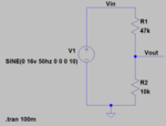
I want to step down a 500V(MAX)/50Hz AC waveform into 3.3V AC signal. In my circuit i can't use a transformer for this process. After that i will rectify the AC into DC by using a precision rectifier.
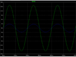
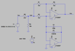
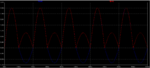
While using a resistive potential divider i can able to step down the voltage as required. But if i use a precision rectifier along with the potential divider, the negative output of the potential divider is getting reduced & the positive remains unchanged. The same thing happens for simulation & real hardware also...
For testing purpose I'm using a (0-15)V/1A transformer with R1=47K & R2=10K. But the potential divider output & precision rectifier output is giving negative voltage with reduced amplitude.
(For precision rectifier, I'm using the reference circuit from "burr brown" single supply circuit)
Please help me regarding this...
I want to step down a 500V(MAX)/50Hz AC waveform into 3.3V AC signal. In my circuit i can't use a transformer for this process. After that i will rectify the AC into DC by using a precision rectifier.
While using a resistive potential divider i can able to step down the voltage as required. But if i use a precision rectifier along with the potential divider, the negative output of the potential divider is getting reduced & the positive remains unchanged. The same thing happens for simulation & real hardware also...
For testing purpose I'm using a (0-15)V/1A transformer with R1=47K & R2=10K. But the potential divider output & precision rectifier output is giving negative voltage with reduced amplitude.
(For precision rectifier, I'm using the reference circuit from "burr brown" single supply circuit)
Please help me regarding this...