Continue to Site

Welcome to EDAboard.com

Welcome to our site! EDAboard.com is an international Electronics Discussion Forum focused on EDA software, circuits, schematics, books, theory, papers, asic, pld, 8051, DSP, Network, RF, Analog Design, PCB, Service Manuals... and a whole lot more! To participate you need to register. Registration is free. Click here to register now.

ac light dimmer light using triac and triac

Status
Not open for further replies.

dumi

Member level 3
Joined
Oct 11, 2013
Messages
64
Helped
0
Reputation
0
Reaction score
1
Trophy points
6
Activity points
387
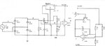
Hi guys,i am using 600V triac with the resistor existing on the dat sheet of a moc 3023,for light dimmer.My light it doesn't come on when unless I take my multimeter and connecting cross pin 6 and pin 5 of moc 3023, I am supplying my moc with 12V from PWM(pulse width modulation) and the current is 1mA
 

As a first step pay attention to the datasheet. MOC3023 trigger current is specified as 5 mA.
 
  • Like
Reactions: dumi

    dumi

    Points: 2
    Helpful Answer Positive Rating
is there a way in which I can up my current to 5mA?

- - - Updated - - -

what other optocoupler can I use which can be powered by with this current?
 

Why are you using a PWM, just fire the MOC from 12v with the suitable resistor for the current rating...
 

will that really help,since my lecture want me to use PWM to adjust because I am doing this for a soft-starter
 

As far as I know,the control of Triac based dimmers can not done using pwm. It is done using zero cross detection circuits and timers. At least that is what i used for my design.
 
  • Like
Reactions: dumi

    dumi

    Points: 2
    Helpful Answer Positive Rating
k,will try it as well.but how coz the zero cross detection can not be adjustable?is yours adjustable?
 

A triac, once fired/trigerred, stays in its on state (conductive) till its (load) current returns to zero (actually be below its holding current). This is why a triac is used with AC voltage so that its current turns off automatically "at" or "after" every zero-crossing ("at" if the load is resistive or "after" if it is inductive).
In brief, triggering a triac (for a light dimmer for example) is phase related and not pulse width related as in case of PWM.

Kerim
 
Last edited:

KermiF is right and that is what I wanted to say. Maybe I didn't make myself clear, let me explain again. You don't need an adjustable zero cross nor an optocoupler with zero cross integrated. What you need is the following :

1- A zero cross detection circuit fed to input interrupt of your mcu (example RB0 on PIC MCU). This can be a simple high value resistor, or you can use an optocoupler with AC input similar to TLP620. I attached a photo of the circuit with the optocoupler, choose R1 and R2 according to your main AC voltage. ZeroCrossOpto.png

2- When the MCU detects the zero crossing, start the timer with the corresponding time according to the dimming level you want. Considering you your AC line is 60 Hz, that gives you around 8.3 ms for each half wave. If you want to dim 50%, the counter should be set to 4.16 ms.

3- When you receive the timer interrupt fire the TRIAC. This will let only the second part of the half wave to your load, thus the light is dimmed to 50% of its maximum. You can see it in the attached image with the red line. wave.png

If you want a soft start than you need to start passing a low percentage of the sine wave until you reach the dimming level needed, ie decreasing the timer every time until you reach the wanted level.
 

I think my MOC is faulty is it possible to test it?if so,how?
 

If you have 5V dc, you can supply its input LED with a current of 5mA by adding a resistor (Rs), in series between Vcc and input:
Rs = ( Vcc - V_led ) / I_led
Rs = ( 5 - 1.2 ) / 5 = 0.76 K
Rs=680R could be used (I_led would be a bit higher than 5mA).
Using an ohmmeter, check if the resistance of its output is high (as being open) before applying the 5mA current.
While the probes of the meter are connected, the measured resistance should become relatively low (not necessarily very low) after applying the input current.
Please note that even if you remove the input current the state of the output (conductive) won't change since its ouput is a triac.
The triac turns off only if the output current becomes lower than its holding current (from datasheet, it is typically 100uA).
These method may not work if the current provided by the ohmmeter is very low (lower than 100uA).
In some multimeters, the diode checker option (position) usually supplies, via the probes, a relatively high current (not less than 1 mA in general).
 
Last edited:

Thanx,
I have attached my full circuit diagram of my design if possible can you please test it for me what could be the fault in it.10-12-2013 12;48;27 PM.JPG2.JPG
 

Attachments

  • 10-13-2013 1;51;29 AM.JPG
    10-13-2013 1;51;29 AM.JPG
    42.8 KB · Views: 165
Last edited:

Sorry, I don't see the MOC IC in your circuit or any other opto isolator IC :(

For instance, isn't U2:A for detecting zero crossing?
I am not sure about the function of the U2:B
 

yes,it is.U2 B is ramp generator,in this case it at as carrier for zero-cross detection

- - - Updated - - -

yes,it is.U2 B is ramp Generator,in this case it at as carrier for zero-cross detection

- - - Updated - - -

all this circuit is connected, I have a zero-cross detection connected with ramp generator and pulse width modulation

- - - Updated - - -

if my moc is triggered by the input voltage,how am I going to see that the LED inside the moc is working?should I have to put my multimeter across terminal 4 and 6?
 

From your circuit (U1:A), the input current is:
I_led = (Vcc - 2*Vd - V_led) / Rs
where:
Vcc = 12V
Vd = 0.7V (2*Vd is the internal drop in LM358 when Vout is high)
V_led = 1.2V (from datasheet)
Rs = 0.12 (on your schematic)
I = 78 mA
Obviously, this calculated current cannot be supplied by LM358. Therefore, it will be limited by the possible maximum current of the IC which is much higher than the typical triggering current of 5 mA.
Let us calculate Rs using the same formula:
Rs = (Vcc - 2*Vd - V_led) / I_led
Rs = ( 12 – 2 * 0.7 * 1.2 ) / 5 = 1.88 K
We can choose Rs as 1K8.

For instance, did you test your MOC IC?

Added:
When the ramp generator is reset by Q1, the ramp voltage starts at maximum.
A note: It is better adding a small diode in series with the base of Q1 so that the reverse voltage of base-emitter junction won't be exceeded when Vout of U2:A returns to ground.
So I noticed that just after the zero crossing, the voltage at the input+ of U1:A is higher than of input- (set by a potentiometer). It means that the MOC is triggered since the start of a new half cycle. In other words, the IN+ and IN- of U1:A need to be exchanged so that the triggering current could be delayed. Instead of doing this, you may like inverting the connection at the output. The LED anode is connected to +12V. Its cathode is conneted to the series resistor Rs then to the output pin of U1:A.
For the latter case Rs is calculated:
Rs = (Vcc - Vsat - V_led) / I_led
where Vsat is the saturation voltage when output is low. We can estimate it as 0.2V
Rs = (12 - 0.2 - 1.2) / 5 = 2.12 K
I suggest using 1K8 which is the nearest lower standard value than 2.12 Kohm.
I_led = (12 - 0.2 - 1.2) / 1.8 = 5.89 mA
 
Last edited:
  • Like
Reactions: dumi

    dumi

    Points: 2
    Helpful Answer Positive Rating
yes, I got 1.2V but not sure about the terminal 1 and 2,how to measure them.

- - - Updated - - -

So, what type of triac should I use and what resistors values I should as a snubber?is everything ok with my circuit?
 

yes, I got 1.2V but not sure about the terminal 1 and 2,how to measure them.

Don't you mean the triac terminals (pin 4 & 6)?

So, what type of triac should I use and what resistors values I should as a snubber?is everything ok with my circuit?

If your load is resistive, there world be no need for a snubber.
About the triac type, you can select one having 400V as rated voltage and 1A as rated continuous RMS current since your load is just 60W. Higher rating current leads to lower gate sensitivity.
 
Last edited:

Not Triac but MOC,how to measure its supply to the gate of triac? and what sort of current should I expect from it?

- - - Updated - - -

can u show me the connection you've explain I kinder get lost.
 

I took Vcc=12V and connect it to the Rs then I connect GND to pin 2 of the MOC it came ON but when I adjust it, It didn't go dimmer.
 

Sorry, what did you adjust? I mean to which circuit you are referring.
 
  • Like
Reactions: dumi

    dumi

    Points: 2
    Helpful Answer Positive Rating
Status
Not open for further replies.

Similar threads

Part and Inventory Search

Welcome to EDABoard.com

Sponsor

Back
Top