Welcome to our site! EDAboard.com is an international Electronics Discussion Forum focused on EDA software, circuits, schematics, books, theory, papers, asic, pld, 8051, DSP, Network, RF, Analog Design, PCB, Service Manuals... and a whole lot more! To participate you need to register. Registration is free. Click here to register now.
These current range to single and three phase motor control using microcontroller?. Can i use ferrite core as current transformer that available in computer SMPS that shown on picture?. if answer is yes. then how many turns used for primary and secondary winding and diameter of copper wire?View attachment 83274
The electrical performance of split-core current transformers is not as good as that of the continuous toroidal coil. The “circle” like (or “ring” like) shape of the toroid usually offers a shorter magnetic path length than other cores. Since the toroids are continuous, they do not add any air gap to the core structure. Split-core current transformers (including toroidal split- cores) add some air gap to the core structure.
**broken link removed**
CT should always be shorted across the secondary terminals. The reason is very high voltages will be induced at the terminals. Think of the CT as a transformer, with a 1 turn primary and many turns on the secondary. When current is flowing through the primary, the resulting voltage induced in the secondary can be quite high, on the order of KV.
From link in post #10 - Part II :
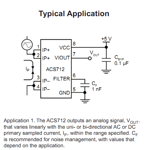
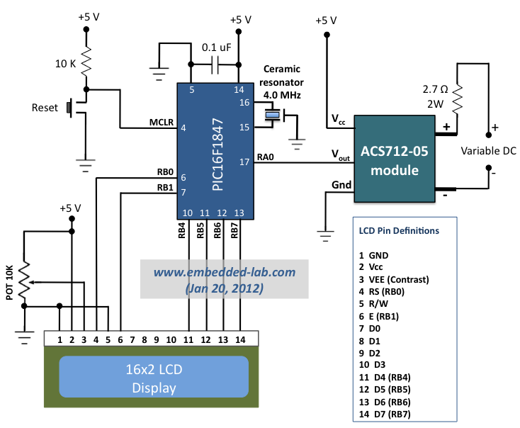
"Keep in mind that the ACS712 sensor provides an instantaneous output corresponding to the current flowing through the conduction terminals. If the current flow is in positive direction (from pins 1 and 2 to pins 3 and 4), the sensitivity of the device is positive, and the ACS712 output voltage rises above Vcc/2. But if the current changes its direction, the sensitivity will be negative and the output of the ACS712 decreases below Vcc/2. This means, for an AC current, the 10-bit ADC output measured by the microcontroller oscillates about 512 counts. Therefore, the microcontroller needs to sample the sensor output fast enough so that the RMS value of the current can be computed from them."
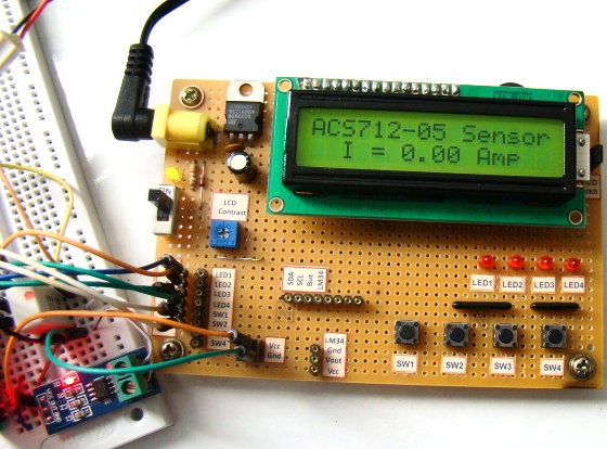
Method of connection to AC is the same. Sensor can meter AC/DC but calc in uC will be different.
This site uses cookies to help personalise content, tailor your experience and to keep you logged in if you register.
By continuing to use this site, you are consenting to our use of cookies.