Continue to Site

Welcome to EDAboard.com

Welcome to our site! EDAboard.com is an international Electronics Discussion Forum focused on EDA software, circuits, schematics, books, theory, papers, asic, pld, 8051, DSP, Network, RF, Analog Design, PCB, Service Manuals... and a whole lot more! To participate you need to register. Registration is free. Click here to register now.

absolute value circuits for high frequency (2MHz)

Status
Not open for further replies.

syamin0712

Member level 1
Joined
Jan 2, 2015
Messages
36
Helped
0
Reputation
0
Reaction score
0
Trophy points
6
Activity points
406
Hi guys,
I need some opinion/comment/suggestion for those who has an experience designing the absolute value circuit.

I have input of sinusoidal signal with frequency 2 MHz and amplitude around 1 Vp-p and I want to make all the negative sign of my sinusoidal input becomes positive.
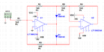
So, what i planning to use is the absolute value circuit. I have found a common use of absolute value circuit as attached.
I'm use op-amp LT1360 because I found that is is suitable for high frequency (2MHz operating frequency) application with slew rate 800V/us and GBw 50Mhz.


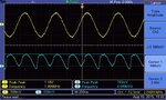
However, I noticed that the final output of my circuit was not smooth as the absolute value or as full wave rectifier.
The result shown that curve of the full-wave rectifier was not same for each period and its not start at 0 V.

Does anybody can give comment on the result that I got? or is it because of the diodes that im used is not suitable?
Thank you in advanced.


regards,
yasmin
 

Attachments

  • lt1360_gmbr.png
    lt1360_gmbr.png
    27.3 KB · Views: 223
  • output_final.jpg
    output_final.jpg
    128.9 KB · Views: 173

I guess your resistors are a bit too low. Or try this schematic.

I think the diodes are suitable. But you can make a full-wave-rectifier without diodes, just with 8 equal resistors:
full-wave-rectifier_without_diodes.png
 

Hi erikl,
Thank you for your reply.
I"ll try to follow your advice.
 

Hi chuckey,

What do you mean by this statement?
"1K from the junction of D1 and R3 to earth"

1)Is it I have to add another 1k resistor to the non-inverting input of the second op-amp? and
2)make it the connection of R3 to ground without feedback again to the inverting input of the 1st op-amp?
 

I don't think that the resistors are too low ohmic for a 2 MHz rectifier. You'll see that diode capacitance is a limiting factor and it's impact increases with higher circuit resistance level. Fast OPs like LT1360 are designed to drive low load impedances (e.g. 150 ohms) and have plenty of output current.

You should definitely use low capacitance schottky diodes instead of 1N4148. 50 MHz GBW looks large at first view, but actual loop gain at 2 MHz is only 25 and a precision rectifier circuit needs a large gain margin to cancel the diode forward voltage.

erikl suggested an interesting rectifier operation principle (OP output saturation instead of diode), but AD8277 is far too slow.

A fast precision rectifier from Analog Devices uses analog switches controlled by a comparator instead of "self-steered" diode switches, another interesting operation principle.
 

Hi FVM,

I'll try to find a suitable low capacitance schottky diode that meet my requirement.
I have search one the diode; BAS69 and will try to simulate my circuit using that diode before implementing it for real circuit.

I'll try also to follow your advice.
Thank you
 

If you consider U1 pin 6, when its at +1V, then it sends current down D1 through R3, when its at -1V it sends current down D2, R2 and R5. So as the currents are different for + and - peaks, the voltage drop across the diodes will be different, hence differing output voltages.
Frank
 

Status
Not open for further replies.

Similar threads

Part and Inventory Search

Welcome to EDABoard.com

Sponsor

Back
Top