c_anicai
Newbie
[Title changed at posters request - Moderator]
https://www.youtube.com/watch?v=SmgJymuPwSw
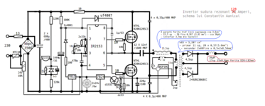
I present to you the simplest scheme of resonant welding inverter that can be made with just a little experience in radio frequency electronics, practically I made it with only an analog multimeter and a frequency generator.
The only adjustment that needs to be made is to set the frequency for the maximum current on a resistance of 0.25Ω at 2-3 Kw using a 1000w/230v bulb inserted on the power supply instead of the 10Amps fuse, the bulb must light up maximum with the load resistance and barely light up briefly. This must correspond to the position of the potentiometer at minimum and if this does not happen it can be corrected from the series resistors parallel to that potentiometer. The frequency is in this case 65 Khz and as we open the potentiometer the frequency drops to about 55Khz thus decreasing the power of the inverter.
https://www.youtube.com/watch?v=SmgJymuPwSw
I present to you the simplest scheme of resonant welding inverter that can be made with just a little experience in radio frequency electronics, practically I made it with only an analog multimeter and a frequency generator.
The only adjustment that needs to be made is to set the frequency for the maximum current on a resistance of 0.25Ω at 2-3 Kw using a 1000w/230v bulb inserted on the power supply instead of the 10Amps fuse, the bulb must light up maximum with the load resistance and barely light up briefly. This must correspond to the position of the potentiometer at minimum and if this does not happen it can be corrected from the series resistors parallel to that potentiometer. The frequency is in this case 65 Khz and as we open the potentiometer the frequency drops to about 55Khz thus decreasing the power of the inverter.
Attachments
Last edited by a moderator: