Continue to Site

Welcome to EDAboard.com

Welcome to our site! EDAboard.com is an international Electronics Discussion Forum focused on EDA software, circuits, schematics, books, theory, papers, asic, pld, 8051, DSP, Network, RF, Analog Design, PCB, Service Manuals... and a whole lot more! To participate you need to register. Registration is free. Click here to register now.

A simple class-A line amp

Status
Not open for further replies.

unitt

Member level 1
Member level 1
Joined
Apr 2, 2013
Messages
32
Helped
0
Reputation
0
Reaction score
0
Trophy points
1,286
Visit site
Activity points
1,518
Hi All
If anything going right you will see a circuit.
I will make a line/ headphone amp, the input is a cd player.
I will no feedback and make it as simple as possible.
You will see one channel.
Mine problem is I don't get it working.
I can adjust the transistor, and get the emitter on 0V,
the basis, I measer 0,7V, and 13V on the collector.
But no amplification. I understand that the basis is not
open enough, 0,7V is too less.
I have tried this with Rc is 5K, 10K, but always the same
result. The transistor is BD441.
The basis R are 100K and 200K
Is there someone who can explain tho get it working?
Thank you very much,
Unitt
 

Attachments

  • Class A Amp.jpg
    Class A Amp.jpg
    575.4 KB · Views: 93
Last edited:

.7v is actually what you should see on the base-emitter voltage. Maybe you've got a bad transistor.

But I have to ask, why would you want to run headphones (or line) off 52 volts (+/- 26)?
 

I can adjust the transistor, and get the emitter on 0V,...
It sounds like the emitter is not connected to 0V. That means R3 must be smaller than R4, so voltage gain is smaller than 1, even with no headphone connected. When you connect a headphone to the output, the gain will be much smaller because the headphone impedance is much smaller than R3.

The output voltage from a CD player is enough to drive headphones very loud, but they often can't give enough current. So you don't really need voltage gain, you only need current gain.

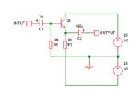
If you want to make a headphone amplifier with only one transistor, it's probably better to use a common emitter circuit something like this.


It would be better to make R2 smaller, say 220R, so more current is available, but the transistor would get very hot unless you use a heatsink.

If you use a lower voltage supply e.g. 9V, you won't have such a problem with heat.
 

Hi Barry
I assum that the base voltage is to low. So I like to know what I must change
to let the circuit working.I have tried with a bfq232, the same result.
I use this I had parts laying around, and I will learning from this problem.
unitt
 
Last edited:

Your headphones will get very little current, with the collector and emitter resistors at those high values.

However if you reduce their value, then they will dissipate a lot of wasted power as heat.

That is, unless your headphones operate on a 26 V waveform.
 

Hi godfreyl
The emitter will I have on virtual ground (0V), R4 compensate R3 and the transistor with -26V. Result 13V over R3, This means the ac out can without distortion not greater than 13V.
To get this lower the base resistors.?? Right?
Unitt

- - - Updated - - -

Hi Breadthead

Mine headphone is an AKG, and need a lot of amplification.
This is the reason why I start this project.
I will do some try out with lower base resisters.
Thanks for your answer.
Unitt
 

The emitter will I have on virtual ground (0V),...
What do you mean "virtual ground"? In the circuit you showed, the emitter is only connected to R4, nothing else.

Also, you said you can adjust to get the emitter on 0V. That means it's not connected to 0V.

Can you show a complete circuit, with all the values shown?
 

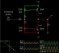
The output from a CD player is probably just a volt or two. To combine both voltage gain and current gain in one stage, can be done but it requires careful adjusting.

Since you show a 26V bipolar supply, it makes sense to use class AB.
The PNP is at the top. The transistors need to be sufficient gain.


It wastes 46 mA when quiescent. This amounts to 8W. You can try to reduce this, but with the tradeoff of introducing distortion.

I made an assumption that your headphones have a few hundred ohms impedance.

It is possible to use class A, however it wastes a lot of power. Components must be rated for dissipating several watts as heat.
 

Hi Bradtherad,
I have see your circuit, and I will give it a try.
I hope within a few days that I get it running
Thanks a lot.
Unitt

- - - Updated - - -

Hi godfreyl.
What I mean with virtual ground is that a point in a circuit is made to 0V.
Not to the real ground.
In mine circuit the neg rail including R4 is used as a bias, to get the emitter
on 0V. And R4=2*R3, when the voltage over R3 is the half of the pos rail.
Then adjust via the base , only this will not give an amplification.
For me is important the way of thinkig, the pactise have tell me I was wrong.
Thanks for your reaction.
Unitt
 
Last edited:

Hi all
I'am not off.
Have a fail in a LM337 reg so it take some time for new parts.
regards
Unitt
 

Hi
After a few errors in a regulator I get it finaly right. I finist wiht the diagram of bradtherad,
so thank you very much for your circuit, and anyone who respont.
regards
Unitt
 

Attachments

  • H-amp.JPG
    H-amp.JPG
    919.4 KB · Views: 65
  • H-amp print.JPG
    H-amp print.JPG
    822 KB · Views: 65

Status
Not open for further replies.

Similar threads

Part and Inventory Search

Welcome to EDABoard.com

Sponsor

Back
Top