Continue to Site

Welcome to EDAboard.com

Welcome to our site! EDAboard.com is an international Electronics Discussion Forum focused on EDA software, circuits, schematics, books, theory, papers, asic, pld, 8051, DSP, Network, RF, Analog Design, PCB, Service Manuals... and a whole lot more! To participate you need to register. Registration is free. Click here to register now.

a problems of analysing the PLL phase noise with PSS+PNOISE

Status
Not open for further replies.

chenmy

Junior Member level 2
Joined
Aug 18, 2006
Messages
22
Helped
6
Reputation
12
Reaction score
5
Trophy points
1,283
Activity points
1,460
relative harmonic pnoise

Hi everyone ,a problems of analysing the PLL phase noise with PSS+PNOISE in spectreRF:

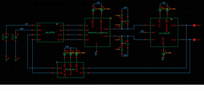
The input refrence is 50MHz and the output is 2GHz with a divider ratio of 40

First I do PSS and set the 'Beat frequency' into 'Auto caculate' (the default Beat Frequency is '50M',which is equal to the input reference frequency)and I set the 'Number of hamonices' into '40'.

Then I do PNOISE ,and in order to see the phase noise near the output frequency of 2GHz,I set the 'Sweeptype' in PNOISE into 'relative' and the 'relative Harmonic' into '40' .

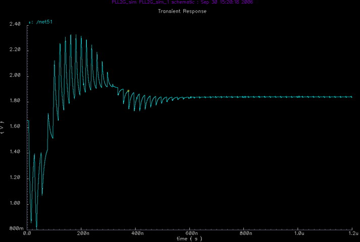
I found the result is not correct,because at frequency more than 10MHz the PLL phase noise got by the above method is even smaller than the VCO phase noise,which is impossible.

Is my PSS+PNOISE setting correct? What should be the correct way of setting PSS+PNOISE if I want to see the output phase noise whith a divider ratio larger
than 1? Thanks a lot!!
 

pnoise relative harmonic

its wrong.The Beat freqency should be set "2G".
 

pll bandwidth frequency sweep

In my Cadence 455, The Beat Frequency could not be set '2G'Hz! Because the PLL has a 50MHz input input frequency and it must be integral multiples of Beat Frequency.

Anybody help with the problem? Thanks a lot!
 

gear2only in oscillator simulation

Hi,

First let me tell you one thing. If you use both input and LO frequency into PSS analysis, generally PSS analysis considers both to be strong signals in the circuit. For that may be QPSS is more better way of doing it, though I am not an expert in QPSS analysis.

For PSS Analysis: For approximate results. Make sure that you have no other strong harminics of LO

Generally input frequency of low amplitude for not producing strong frequency transformation in the circuit. You have to connect a Vsource for the input and set it as DC. Now only LO will remain in your circuit. The strong harmonics are only generated thorugh LO and in practical cases the noise transformation to other frequencies due to the interference of the input frequency can be nenglected. Hence I suggest you to check this method. Feel free to post if you have any doubt about settings.
 

    chenmy

    Points: 2
    Helpful Answer Positive Rating
pnoise shooting small signal analyses

gunturikishore, Really thank you for your help!!

But I am still confused .If I set the input into DC, my PLL will never locked so the Periodic Static State will never be achieved.How can I use PSS+PNoise?

What about setting the input as "small" pulse in 50MHz?

Waiting for your advice.Thank u!
 

site:www.edaboard.com pll phase noise

Hy chenmy. I must ask you why you are measuring noise near the 40th harmonic? The area of interest is always near the fundamental, a.k.a. 1st harmonic, so you must set the sweep relative to harmonic 1 into the pnoise form.
I am waiting also for gunturikishore to explain in detail the correct way of setting the testbench for noise analisys of the whole PLL. We can always learn from someone who already done that (I didn't...)
PS: I think also that the correct beat frequency must be set to 2GHz.
 

pnoise is not converging

The combination of PSS and PNOISE analysis definitely needs some more insight here. I never used PSS for PLL. But let me try it.

As far I can see, you must include the 50 MHz source for your PLL to work. For PSS analysis to converge, that is necessary. Any voltage source will be identified by the analysis automatically. So your small pulse source will not work.

Now I think you must include both the sources in ur PSS analysis.

The prblem for u, as far as I can see is your relative sideband. When you give reltive it creates the noise required for the PNOISE analysis around that side band, for example if you give 0 to 10MHz sweep, it will create the noise at 2GHz + 10MHz. Now this in mixed with the already generated SPECTRUM in the PSS.(You should be knowing the correlation if u learnt DSP, which is the opration actually done in mixing here)

So please check that you are creating your noise in the appropriate band. IT WILL BE DISPLAYED IN THE OUTPUT LOG FORM IN BEFORE THE PNOISE ANALYSIS. If you are generating the noise around 2GHz, and if your PSS previously contains strong harmonics around 2 GHz, it will be down converted to the frequencies arond zero, which is the case I can see for u.

Please post your response after checking as it will help me to see whether my assumptions are correct or not. Thank You.
 

pnoise absolute sweep

OKay! gunturikishore,let me tell u my flow in more detail:

Setp 1: use DC source as the input reference

Step2: set PSS 'Beat Frequency' to 2 GHz and Choose 'Oscillation' and the output voltage is the VCO Diferential output .Also,I set the 'Tstab' long enough.

Step3: set PNoise The noise frequency sweep range From 10kHz~10MHz .As u kown ,this will be mixed to 2GHz+10KHz~10MHz

Okay!Run!
Result : My PLL can not be locked .PSS do not converge, Pnoise can not be implented!
I plot the VCO control voltage ,it is always falling so I think if the DC source is used as input reference my PLL would never be locked so it is impossible for PSS to converge.

Added after 15 minutes:

Because the 50 MHz source must include for my PLL to work,So I tried another way:

Step 1: Use 50MHz pulse source as input.

Step 2: In PSS , set the Input signal to 'Small' (U kown ,the default value for any input signal is 'Moderate' However,you can change it to either 'Strong' or 'Small')

Step 3: Set the PSS 'Beat Frequency' to 2GHz. (This time 2GHz is acceptable by PSS because my input is a 'Small' 50MHz pulse source) and Set the output voltage the VCO Diferential output.Also,I set the 'Tstab' long enough.

Step 4: In Pnoise,set the noise frequency sweep range From 10kHz~10MHz

Okay!Run!

Result:My PLL is locked ! But the PSS still does not converge.

My conclusion is :even when my PLL is locked, the output frequency is still not stable,because the ripple of VCO control voltage exist!
So I think PSS is not suitble for a locked PLL .

Hey,everyone,waiting for ur reply! Thank u all!!
 
qpss tips simulation

Please read my previous post. Include the two sources and set the beat frequency to 50MHz.

If you really give two sources in the circuit and try to set a beat frequency of the larger one, the simulator should give an error message before simulation. Check that your sources are identified correctly in the PSS form. I saw in the past that it accepts by chance, but ideal behavious is that it gives error message.

If you can provide a small block diagram of your PLL that will be useful to understand betterly.

If you are sure that your circuit does not have periodicity you should switch to QPSS analysis instead of PSS.

I dont know whether you included any random sources or something like that but I dont believe that it does not have a periodicity until all the sources in the circuit have periodicity.

I can give some more tips like if your convergence is ocillating at the same node(s) between negative and positive values, change your integration method to Gear2only from TRAP in the options form provided in the bottom of the PSS form. That will help in the convergence.

But if you are giving 2 GHz as beat frequency even after adding the 50 MHz source, I assure you it will never converge.

Added after 21 minutes:

I forgot to add, PLL generally includes charge pumps etc. which take some time to charge initially. So please give the circuit a settling time equal to the beat frequency time period, for proper convergence of the PSS analysis.
 
phase noise relative harmonic

Hi,

I was just checking the option of Medium and Small sources in PSS analysis. I dont find any such option in my IC 5.141. I doubt PSS accepts any other sources apart from Large. May be they included that similar to QPSS analysis which is corrected in the later version. I checked the documentation from Cadence also. It states that the PSS is large signal analysis and QPSS is suitable for medum and small sources. So I suggest you not to believe that even if the form accepts small or medium sources, the analysis is going to accept at the background such sources. Thank You. ALl that is the clarification I can make for now.
 

pnoise relatve harmonic

gunturikishore,I know that u suggest me put 2 sources :eek:ne is the 50MHz input, the other is 2GHz LO,and then set Beat Frequency to 50MHz and do PSS.

My confusion is that the PLL does not need 2GHz LO to work .What the PLL needs is only the 50MHz input and it will generate a 2GHz frequcncy at the output .

And what I wanna do is to analyse the phase noise near the output ,from 2GHz+10kHz to 2GHz+10MHz.

Do u think still ur assumption is valid?Give me some suggestion ,thank u very much!!

Here is my PLL entire block,note it has differential inputs (most left)and outputs(most right).
51_1159495948.jpg
 

multiple clock qpss

Hi,

Though I can not see the names of the blocks very clearly what I understood is you have a 50 MHz ideal frquency tuning input, followed by charge pump, which feeds the 2GHz free running VOltage controlled oscillator. The oscillator output is is divided by a 40 circuit to again to 50MHz and given again to the input block for comparision with the reference frequency. Am I right to that extent?? plaese confirm.

Now I can suggest you two ways of doing it, please try them. If you can post the result I also can learn some thing from that as there is no mention of PLL in the documentation also.

In the first method, as far as I can see you are interested in the phase noise of the VCO at 2GHz. There is no frequency input to this block at 2GHz. THere is no chance of any noise coming to this block as the block preceeding to it is a charge pump which should be acting as a LPF. Hence you can run only the VCO independenly with a fised voltage tuning input. The analysis of this is like Oscillator simulation explained in the manual. The oscillation frequency is decided by the speciaaly expalined oscillator analysis in the SPECTRERF manual. In the same manual PNOISE analysis is also specified.

Second method is the full simulation. I doubt about this simulation convergence but seems possible if your PLL is locking to the input frequency correctly. Connect the input 50 MHz sources and specify the BOTH differential sources in the form. Differetial sources dont make any differece until both of them are of same frequency. Now set the number of harmonics to a maximum of 120 0r 80 in PSS form, so that atlest three or two harmonics of the LO are taken into account. Please specify integration method as Gear2only as TRAP may be problematic for such a highly complicated circuit. Set accuracy to moderate or accurate depnding on the simulation time. RUn the PSS simulation. Give aliitle TSTAB as much as 200ns for the circuit to stabilize.If it completes successfuly, observe the obtained output spectrum after each block. Note down the highest harmonics because it may help in analysisg later for PNOISE analysis.

Now for PNOISE analysis set the option as absolute. You are not looking for any frequency transformations here. Just you need to observe for the entire bandwidth from input sources to the output, the frequencies whcih are transforming to 2 GHz or for that any other frequency, from input to output. Hence give entire range from the 10 Hz to some 5 GHz. No extra time for this range generally as the operation is just linear here.

Since PNOISE analysis includes the device noises and corresponiding noise transformations due to non-linerities in the circuit as mentioned in the documantation, I expect that this analysis if at all completes should match with the result of the previous method. SO your ouptput spectrum also is from 10 Hz to 5 GHz as u mention the sweep as absolute. You shoud be able to observe peak noise at around 2 GHz for the VCO output. Dont get confused if it shows some very high peak at the oscillation frequency.

PLL analysis is very complicated as far as I heard. I am just a learner in the field. Please dont blame if I could not reaaly help u out after a long discussion.
 
pnoise ideal switch

Hi,gunturikishore,I am really thankful to u because u have helped me a lot!
And I think we are now standing very close to the truth.

ur analysis of my circuit is right .The only thing I should point is that before the charege pump there is a phase frequency detector.

I think I will try the 2nd method tomorrow and post my result (if 1 day is long enough for the simulation) so that everyone could learn something from it.

Thank you.
 

qpss vco phase noise simulation

Hi,
I have tried the 2nd method with Cadence 4.55 and here is the report:

I did it for 4 times with different numbers of harmonic in PSS of 400,120,80,40

I specify the 'tstab' as 1u, which is long enough for my PLL to be stable.Please See The Figure below.

I specify the 'integration method' as 'Gear2only' for efficient convenge and the 'maxacfrequency' as 10G to increase the iteration number.

I set accuracy to 'moderate' or 'liberate'.

The result is: For larger harmonics (400,120,80) PSS fails to converge .For smaller harmonics (40) the PSS converges after 5 iterations.

However,I think the harmonic number of 40 is too small for an accurate phase noise analysis.Because the noise near the multiple frequency of 2GHz (For Example,4GHz, 6GHz,8GHzand higer) will be folded down to the phase noise near 2GHz. So I think if I want to analyse the phase noise more accurately,the harmonics in PSS should be specified at least as 200 so that in PNOISE I can take the the noise near 10GHz into account.Then the circuit is too complicated for PSS to converge.

By the way,gunturikishore,I think the first method is only valid for analysing phase noise at a frequency offset higher than the PLL bandwidth as VCO noise will dominate at that frequency.However,below the PLL bandwidth,charge pump noise will dominate.So I did not try the first method.But thank u all the same.

I think I will use some behavior model to take the place of the block,such as Divider and PFD,which are not so important to the phase noise contribution.

Other suggestion will be appreciated.

93_1159605035.jpg
 

pnoise integration method

As PSS analysis is converging to certain extent circuit is locking well. QPSS will help with all the sources set to high. Timing constraints are not so tight in the QPSS as far I expect hence shoud definitely converge. But it is difficult to believe the analysis as the Cadence SPECRERF document does not provide a good explanation of this analysis.

One more thing to note here you need not to give such a long settling time as PSS uses automatically shooting methods to reach the final steady states of the circuit. It will be useful when the reset and clocks in the circuit are a little delayed.

Generally one more thing I will do is set the analysis period such that there are no abrupt transitions of the clock like 50MHz frequency in this case at the start and end of the analysis period. I will set the settling time as 25 ns so that the analusis is taken between 25 ns and 45 ns. It is neither positive nor negative edge of any clock. Since for PSS to converge the intial and final values matching is important it will not cause unnecessary disturbece for the analysis, while converging.

If possible trying to set the initial values of the important nodes like the expected voltage of Phase Frequncy detecting circuit in this case will help the simulator in settling to the final value very quickly.
 
Status
Not open for further replies.

Part and Inventory Search

Welcome to EDABoard.com

Sponsor

Back
Top