Continue to Site

Welcome to EDAboard.com

Welcome to our site! EDAboard.com is an international Electronics Discussion Forum focused on EDA software, circuits, schematics, books, theory, papers, asic, pld, 8051, DSP, Network, RF, Analog Design, PCB, Service Manuals... and a whole lot more! To participate you need to register. Registration is free. Click here to register now.

A problem in frabrication: Narrow band filters

Status
Not open for further replies.
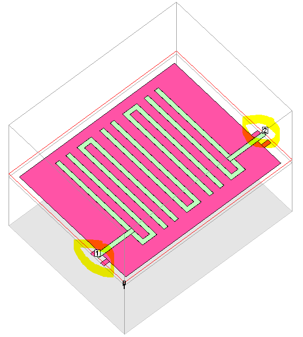
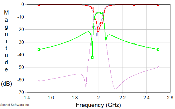
I checked what the effect of mounting the SMA connectors with a gap is. The stopband rejection is degraded, but the passband performance does not change too much. So this connector issue does NOT explain the measurement results.


Regarding the CST settings: I am not a CST user, so I am not sure if these settings are complete. Maybe someone else can comment.
With the metal thickness, the 1.75µm look wrong and should be 17.5µm.
 

I have the same suspect with u, but I am not sure about how is good job on soldering at the connectors SMA? There are some images of my design and it's results, the real filter is also captured in the following:
View attachment 78671View attachment 78672View attachment 78673
Would u like to give me some advices on soldering at the connectors SMA?

- - - Updated - - -


Please give me more details when u said "the filter is not correctly tuned"? and also thank so much for your helps!

That Ripple in your "Measured S21" (Black Trace) looks like you have a bad
Cable/cal. Make sure the cables are all tight and re-Cal. You SMA connectors could
be better.
1) Eliminate that air Gap
2) Trim the center pin of the SMA (that touches the PCB).
3) if you can cut the center pin to slope down towards the PCB, Having a smooth
Transition is better.
4) Make the solder smooth and as thin as possible.
 

In my opinion CST is not the easiest tool to simulate this kind of filters. I would be better use a palanar simulatore like sonnet, or emsight.
Again in my opinion the right disign procedure for this kind of circuits is: design the filter with the linear simulator, make a yeald analisys respect the fabrication tolerances and then check the design with the EM simulator. Another important thing is to take care about the measurement: If you design and the EM simulate a filter inside a box, you must test the prototipe in the same box.

Ciao.
 

Status
Not open for further replies.

Part and Inventory Search

Welcome to EDABoard.com

Sponsor

Back
Top