Continue to Site

Welcome to EDAboard.com

Welcome to our site! EDAboard.com is an international Electronics Discussion Forum focused on EDA software, circuits, schematics, books, theory, papers, asic, pld, 8051, DSP, Network, RF, Analog Design, PCB, Service Manuals... and a whole lot more! To participate you need to register. Registration is free. Click here to register now.

a hybrid 2 to 4 wire telephone circuit

Status
Not open for further replies.

polarized

Member level 4
Joined
May 13, 2002
Messages
76
Helped
0
Reputation
0
Reaction score
0
Trophy points
1,286
Location
Europe
Activity points
966
2 - 4 wire hybrid

Hi all,

Is there an electronic circuit which can split the transmit and the receive audio which exist together on a fixed telephone line(a telephone pair) into two completely independent sections: transmit section and receive section ? I already have a couple of circuits, but would like to have more of them. I would like to use standard components which can easily be found, because some of the DAA special integrated circuits for this purpose of interfacing the telephone line are difficult to find.


Regards.
 

two methods

There are two general methods. One uses center tapped transformers. The other uses op amps. If you have these, you have the lot.
 

2 to 4 wire converter with operational amplifiers

Hi flatulent,


I have a couple of schematics, but they use the center tapped 600:600 ohm transformer. If its not a problem could you send me an electrical schematic of the 2 to 4 wire converter which uses operational amplifiers? And also how does the version of the 2 to 4 wire converter with operational amplifiers actually work?


Regards.
 

years ago

I saw the circuit in an application note years ago and do not remember the details. In general, there was some form of adding the transmitter signal to the receiver through a nulling route.
 
  • Like
Reactions: GUSTA

    GUSTA

    Points: 2
    Helpful Answer Positive Rating
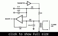
Maybe you are looking for something like this:
 
  • Like
Reactions: GUSTA

    GUSTA

    Points: 2
    Helpful Answer Positive Rating
hey guys i am also looking for 2 wire to 4 wire converter i wonder if you ever found it?


---------- Post added at 14:58 ---------- Previous post was at 14:52 ----------

Hi flatulent,


I have a couple of schematics, but they use the center tapped 600:600 ohm transformer. If its not a problem could you send me an electrical schematic of the 2 to 4 wire converter which uses operational amplifiers? And also how does the version of the 2 to 4 wire converter with operational amplifiers actually work?


Regards.


Find an old dial-up modem that is not used anymore and steal its transformer.
Or take one from an old telephone answrering machine.
Or from an old speaker-phone?
 

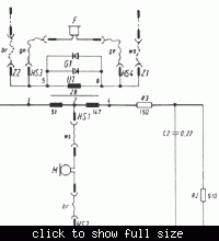
Unfortunately, the shown transformer circuit is not operating as a hybrid.
 

from my understanding 2 wire have transmission bydirectionally, and 4 wire have 2 balanced pair TX and RX. Shown schematic shows as one of the pairs is ground. Now is this still balanced. Another question: is the headphone jack is 2 considered as 2 wire?
 

For a balanced hybrid, you can e.g. refer to the double-transformer hybrid. See: Hybrid coil - Wikipedia, the free encyclopedia

Please, notice, that a passive hybrid has also to keep some impedance relations to work correctly.

Here's a classical analog telephone hybrid circuit for reference. The complex termination and transformer winding ratios make it appear somewhat mysterious, but it's following a simple principle:
 

amjadali56,

Thank you. Your diagram shows one directional transmission. Whould it work for transmission bydirectonally? In settngs referring to of truks and telphone circuits and bydirectional voice trasmsion.? Thank you again.

from my understanding 2 wire have transmission bydirectionally, and 4 wire have 2 balanced pair TX and RX. Shown schematic shows as one of the pairs is ground. Now is this still balanced. Another question: is the headphone jack is 2 considered as 2 wire?
 

the one on 12# is cool but what's the value of the transformer and the amplifier is 741?
 

but what's the value of the transformer and the amplifier is 741?
The internal resistor 620 ohm, so the transformer should be 1:1 for best hybrid opperation. 741 should work.
 

what do u mean by 1:1 ... as i know transformers are measured by its transfer from voltage to another otherwise if it is a coil so it's measured by henry.
 

what do u mean by 1:1
Really no clue? The specification seems self-explanatory in my view. Of course it doesn't fix all transformer parameters. But specifying just the windings ratio is quite common for audio transformers. 600 ohm:600 ohm would be another popular specification.
 

so here it is i have to use this equation : Z(impedence)=j*2*3.14*f*L
Z on each side is 680 ohm / f is frequency and it's about 3000Hz on the phone so L will be 36mH on each side of the transformer so it's to coils with a ferite between them and each coil is 36mH...
is this right???
 

The impedance of the telephone line should be real (resistive) and frequency independent in a first order. So 30 mH transformer main inductance is surely inappropriate. The inductance should be large enough not to reduce the nominal 600 ohm value too much in the frequency band of interest (300 Hz - 3 kHz). L > 1 H is suggested.
 

that looks interesting and i'll try it as soon as i get the elements... but i would like to understand more about it : so u said that the impedance should be real (not imaginary) so how did mentioned to make it that big >1H what's the rule to make it real impedance instead of imaginary?
 

The real impedance is set by resistors at both peers. The transformer inductance is effectively connected in parallel to the line impedance and must not be too low. 1 H transformer inductance results in a cut-off frequency of about 100 Hz with 600 ohm line impedance, so it' on the safe side.

fg = L/(6.28*R)
 

Status
Not open for further replies.

Part and Inventory Search

Welcome to EDABoard.com

Sponsor

Back
Top