henry kissinger
Member level 2
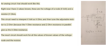
I am thinking about a analogue circuit that should work like this.
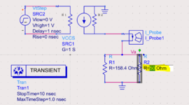
Right now I have 2 values known, these are the voltage of a node (38V) and a resistor (158.4ohm).
This circuit need to interpret 38V as 38ohm, and then tune the adjustable resistor to 50ohm (because the 158.4ohm and 50ohm in parallel give us the 38ohm resistance.
Any idea is appreciated.
The result circuit should work for all the values of known values of the voltage node and the resistor.