wf1318
Newbie level 4
step up voltage circuit
Hello!
I have looking for a "low DC to high DC" voltage step up circuit long long time.
Fortunately, I found my "Cooler Master Musketeer III" Tube Headphone/Pre amp have this voltage step up design on the circuit board.
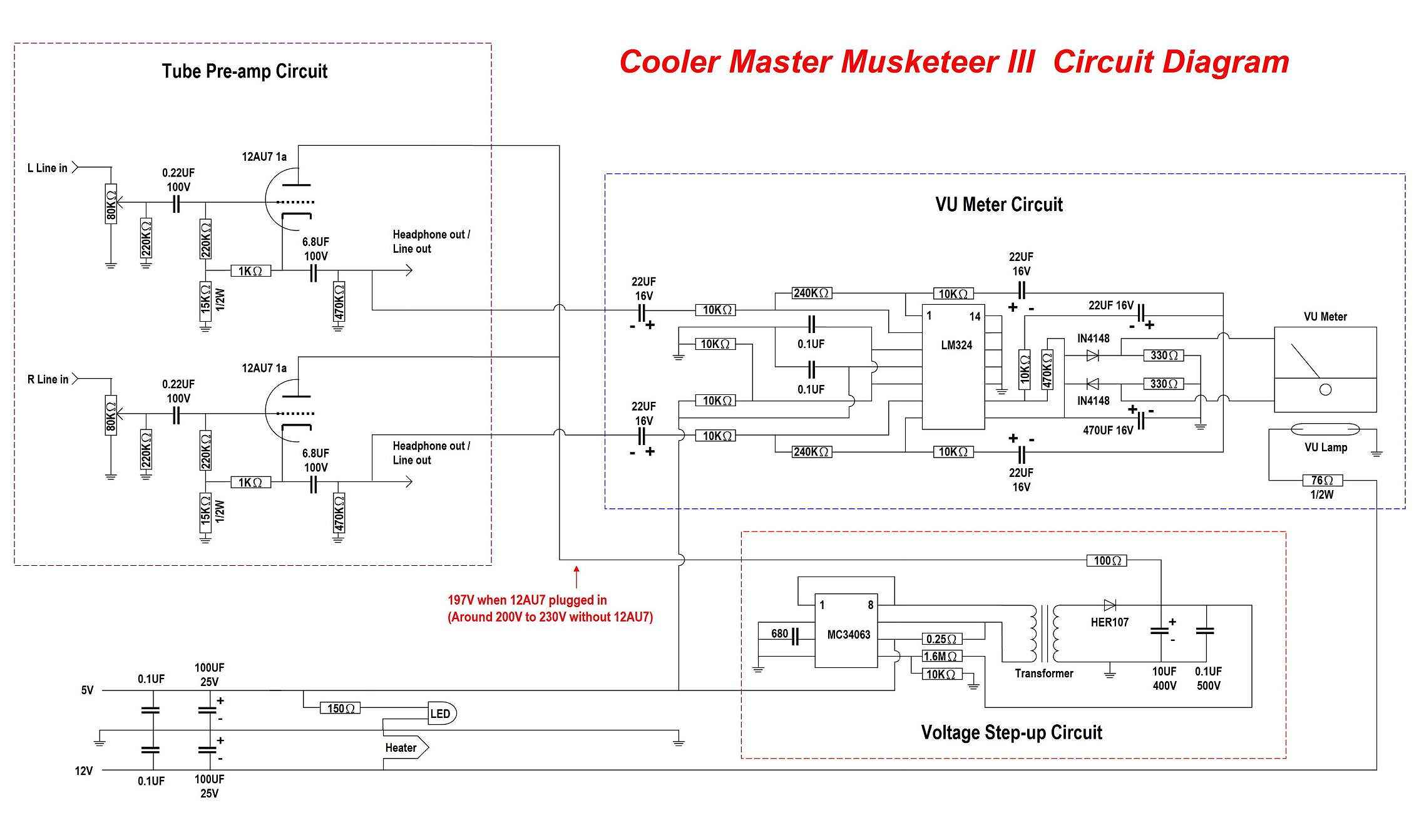
And I draw the whole diagram of this circuit.
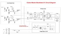

As you see, a 5V DC step up to around 200V DC via a MC34063 with a few electronics parts and a little transformer.
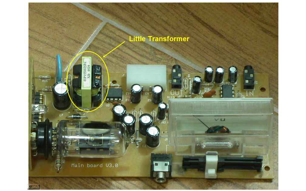
The kind of transformer is not the general transformer like 220AC to 12AC transformer...
Here is my questions:
1.) What kind of this little transformer called?
2.) How to calculate (may be how to guess) the ratio between 1st & 2nd winding of that transformer?
Because I can't find any value mark on the transformer, only the product number mark on it.
3.) This kind of transformer is really hard to find......so, can I build it by myself? If yes, how to do it?
Or can I modify the general "AC to AC transformer" to do this job?
Hello!
I have looking for a "low DC to high DC" voltage step up circuit long long time.
Fortunately, I found my "Cooler Master Musketeer III" Tube Headphone/Pre amp have this voltage step up design on the circuit board.
And I draw the whole diagram of this circuit.
As you see, a 5V DC step up to around 200V DC via a MC34063 with a few electronics parts and a little transformer.
The kind of transformer is not the general transformer like 220AC to 12AC transformer...
Here is my questions:
1.) What kind of this little transformer called?
2.) How to calculate (may be how to guess) the ratio between 1st & 2nd winding of that transformer?
Because I can't find any value mark on the transformer, only the product number mark on it.
3.) This kind of transformer is really hard to find......so, can I build it by myself? If yes, how to do it?
Or can I modify the general "AC to AC transformer" to do this job?