Continue to Site

Welcome to EDAboard.com

Welcome to our site! EDAboard.com is an international Electronics Discussion Forum focused on EDA software, circuits, schematics, books, theory, papers, asic, pld, 8051, DSP, Network, RF, Analog Design, PCB, Service Manuals... and a whole lot more! To participate you need to register. Registration is free. Click here to register now.

9V battery power supply - add dc adapter backup

Status
Not open for further replies.

pedalpower

Junior Member level 1
Joined
Sep 1, 2016
Messages
19
Helped
0
Reputation
0
Reaction score
0
Trophy points
1
Activity points
173
Hello,
I need help with this build.
I would like to build battery power supply for my guitar pedal board. Here is a requirement.
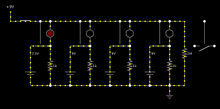
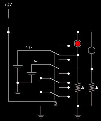
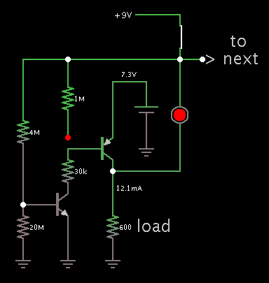
four 9v battery, isolated one for one effect pedal. When pedals are not in use, all battery must be disconnected fron the pedals, as soon as pedal board powers on battery should kick in and provide the power to those pedals. When the power of the battery drops to some point, power supply has to provide back up, untill the battery will be replaced with new one. Each output dedicated to certan pedal. Here are the pedal current: first 11.73ma second: 1.78ma third:8.4ma fourth: 4.5 ma I prefer to use comperators and need some help with schematiss.
I'll provide more info if needed.
Regards and thanks for your help.
 

Hi,

To simplfy this... i'd use a single battery with enough energy to be able run the whole system (much) longer than you need.

Maybe one of those USB battery packs.
I think they have enough power to run your system for days..
And you don't have to take care about charging...this is all built in....and they are cheap. Maybe they have some indicator for health status.

All you need are some DC/DC converters that make 9V from the 5V...and some filters to clean the 9V.

Maybe try AM1D-0509SZ. They are not very high sophisticated regarding noise and standby current.
But there are other manufactureres of similar devices with different quality..

Klaus

Hi Klaus, Thanks for reply. Unfortunatelly a pedal builder ( Pete Cornish ) warned me to use 4 separate 9v batteries insead of one. Mason Marangella made those battery power supplies using comparators ( looks very simple, one in, four outs and I think two comparators). Should be some resistors there but I can't see them on a picture. Top of comparators covered by black foam. No PCB board. Any idea how to make it work.
Thanks, Regards,
Iouri
 

Hi,

I´m confused. Ples draw a picture of what you want to build.

1 battery or 4 batteries?

A comparator is no power supply. I don´t know how this should work with a comparator.

black foam, no PCB. --> I´m cold. Not my way of designing electronics.

Klaus

- - - Updated - - -

Added:

I just saw some pictures of Pete Cornish`s work.

He may be a good designer for effect equippment. He surely has the experience how to make good sound.
But the wiring and the many small PCBs in one device .. is not how one does it nowadays (Btw: today one rather likes to create the effects digitally. Not saying this is worse or better).

You may rely in his experience or not. There are many ways.

For us: To be able to give valuable advice, best is to know the connections/schematics of each device.

Klaus

Hi Klaus, Battery Pack.jpg

Here is a picture of working unit:
9v power supply connected to first outlet and LED lights up when 9v dc presented there from power adapter. All four 9 v battery become connected to each dedicated effect pedal ( outlets 2 3 4 5). Those effect pedals powers by battaries. When 9v from power adapter removed, all battery disconnects from the pedals. If one or more batteries drops the voltage over 7 volts, power adapter input will take that outlet over and will provide a power to the pedal or pedals, allow to use the pedals to compleat the show insead of loosing audio. Top lead of the battery housing allow to replace the battery very quick with no need to remove the pedals from the pedal board, disconnect the jacks etc.
Please let me know if I missed something.
Thanks,
Iouri
 

If one or more batteries drops the voltage over 7 volts, power adapter input will take that outlet over

The easy way to do this is to install one 9 V supply, connect it through an led to each battery. The supply is idle until one of the batteries drops to 7.3 V. Then the supply starts to provide power.

The led's do two functions: (a) light up to tell you when a battery is low, (b) steer current so that batteries are electrically separated.
 

Hi,

What's the basic goal if the circuit?

When 9v from power adapter removed, all battery disconnects from the pedals
This means when the power from adapter is removed, then everything is dead. No music, even when the batteries are good.

Btw: usually with audio equippment on the stage one wants to avoid ground loops. I don't know the wiring of the box, but it seems it creates ground loops. Can you confirm this?

Klaus
 

The easy way to do this is to install one 9 V supply, connect it through an led to each battery. The supply is idle until one of the batteries drops to 7.3 V. Then the supply starts to provide power.

The led's do two functions: (a) light up to tell you when a battery is low, (b) steer current so that batteries are electrically separated.

Hi, is it possible to draw a schematics. As fare as I understand when the supply starts to provide the power it also bring a voltage to battery, bad idea. Correct me if I'm wrong. Another thing is, when the pedal board not in use, the battery must be disconnected to prolong the batteries life.
Regards,
Iouri
 

Hi Klaus, No ground loops, all four battery outputs isolated. And you right, when the power from adapter removed, wholl pedal board is dead and batteries are disconnected from the pedals to prolong a battery life.
Thanks
 

when the pedal board not in use, the battery must be disconnected to prolong the batteries life.

Sorry, that slipped my mind while I wrote my post #6.

To connect and disconnect 4 batteries requires a 4-pole switch or relay (or 4 switches, or 4 relays). It might be possible to use transistors/mosfets. Your idea sounds good, and it's a good idea to have redundancy, however the quantity of power sources starts to get cumbersome. It sounds good to include components to enhance reliability, however we also automatically increase the number of things to go wrong.

pedal current: first 11.73ma second: 1.78ma third: 8.4ma fourth: 4.5 ma

These are low current levels, and a single supply could handle the total load (as post #2 suggests). Then you only need a 1-pole relay or switch. In addition there are jacks for guitar pedals, which contain a switch which disconnects the battery when you remove the cable plug.
 

pedal.jpg
Sorry, that slipped my mind while I wrote my post #6.

To connect and disconnect 4 batteries requires a 4-pole switch or relay (or 4 switches, or 4 relays). It might be possible to use transistors/mosfets. Your idea sounds good, and it's a good idea to have redundancy, however the quantity of power sources starts to get cumbersome. It sounds good to include components to enhance reliability, however we also automatically increase the number of things to go wrong.


These are low current levels, and a single supply could handle the total load (as post #2 suggests). Then you only need a 1-pole relay or switch. In addition there are jacks for guitar pedals, which contain a switch which disconnects the battery when you remove the cable plug.

You right, but I prefer to find out the way it was done by Mason, the emage of the working unit is attached. Wholl idea is to minimize the size of pedal board and never moved the pedals to change the battery and the same time just plug and play. Here is a picture of my pedal board I built myself and you can see how close are the pedals to disconnect the cable plugs. If I will not find out the way to make it like Mason did, I'll install relay or switch to do it manually.
 
Last edited:

This simulation appears to take care of your requirements. The analog switches close when backup power is available. The switches connect four 9V batteries to their loads (1k resistors).

Notice the first 9V battery has drained so it is down to 7.3V. The backup is starting to deliver power, as shown by the led.


The analog switches are a cheat. They simplify the appearance. (At right is a lone example.) In hardware you would replace them with four PNP transistors, or a 4-pole relay. Possibly a 4066 IC (quad bilateral switch).

As fare as I understand when the supply starts to provide the power it also bring a voltage to battery, bad idea.

For a while each delivers some power (the backup some and the battery some). However you are correct because it is true that an alkaline battery is prone to leak corrosive liquid if current goes in reverse direction through it. This could happen if battery chemistry deteriorates to the point where its internal EMF goes below 7.3 V. Supposedly the led will notify you before that time.
 

This simulation appears to take care of your requirements. The analog switches close when backup power is available. The switches connect four 9V batteries to their loads (1k resistors).

Notice the first 9V battery has drained so it is down to 7.3V. The backup is starting to deliver power, as shown by the led.


The analog switches are a cheat. They simplify the appearance. (At right is a lone example.) In hardware you would replace them with four PNP transistors, or a 4-pole relay. Possibly a 4066 IC (quad bilateral switch).


For a while each delivers some power (the backup some and the battery some). However you are correct because it is true that an alkaline battery is prone to leak corrosive liquid if current goes in reverse direction through it. This could happen if battery chemistry deteriorates to the point where its internal EMF goes below 7.3 V. Supposedly the led will notify you before that time.

Great, I love this idea. Sorry I have no knowlage with electronics. I'm assuming I have to connect pedals intead of 1k resistor, correct me if I'm wrong. I'll givoe it a try with 4066IC first because it looks easy way to me. I'll create wholl schematics just with one battery on a breadboard to check how it will go, assuming there is no difference how many batteries I'll connect later. Is this correct? Also if I have to try a relay, where shuold I have to connect a relay's coil and what voltage relay I have to use.
Thanks
 

This simulation appears to take care of your requirements. The analog switches close when backup power is available. The switches connect four 9V batteries to their loads (1k resistors).

Notice the first 9V battery has drained so it is down to 7.3V. The backup is starting to deliver power, as shown by the led.


The analog switches are a cheat. They simplify the appearance. (At right is a lone example.) In hardware you would replace them with four PNP transistors, or a 4-pole relay. Possibly a 4066 IC (quad bilateral switch).


For a while each delivers some power (the backup some and the battery some). However you are correct because it is true that an alkaline battery is prone to leak corrosive liquid if current goes in reverse direction through it. This could happen if battery chemistry deteriorates to the point where its internal EMF goes below 7.3 V. Supposedly the led will notify you before that time.

Also forgot to ask, what PNP transistors I should use in this aplication?
Thanks,
 

I'm assuming I have to connect pedals intead of 1k resistor

Correct.

where shuold I have to connect a relay's coil and what voltage relay I have to use.
Thanks

Here's how to hook up a relay. (You may need to use 2-pole or 1-pole type, whatever you can find.) The relay coil should be rated 9V. The schematic shows 2 pedal circuits.

3784392400_1472946008.png
 

Correct.


Here's how to hook up a relay. (You may need to use 2-pole or 1-pole type, whatever you can find.) The relay coil should be rated 9V. The schematic shows 2 pedal circuits.

3784392400_1472946008.png

Have put everything in a solderless breadboard and everything seems to work fine. Only one battery at this time. I've used Omron G5V-2-H1 9VDC relay. Should I use two of them to get all four battery outputs isolated, I think I can't get it with just one relay. Also what is a purpose of 1mgom resistor acros the + and - terminals, should I use it with the relays or not.
Thanks a lot.

- - - Updated - - -

Have put everything in a solderless breadboard and everything seems to work fine. Only one battery at this time. I've used Omron G5V-2-H1 9VDC relay. Should I use two of them to get all four battery outputs isolated, I think I can't get it with just one relay. Also what is a purpose of 1mgom resistor acros the + and - terminals, should I use it with the relays or not.
Thanks a lot.

And probabelly last question. How to make it possible to provide particular current to each output. Let say output one has to provide no more then 1.78ma, out two 1.58 ma, out 3 6.83ma out 4 8.4ma and if I need one more it hase to be out5 4.5ma
Thanks.
 

Should I use two of them to get all four battery outputs isolated

Of course you can use as many relays as you need to do the job.

Also what is a purpose of 1mgom resistor acros the + and - terminals, should I use it with the relays or not.

It's a pull-down resistor needed in the simulator to turn off the analog switch. It is unnecessary with a relay but there can be some circumstances where you need a pull-down or pullup resistor to ensure stable performance.

How to make it possible to provide particular current to each output. Let say output one has to provide no more then 1.78ma, out two 1.58 ma, out 3 6.83ma out 4 8.4ma and if I need one more it hase to be out5 4.5ma
Thanks.

Your pedals use these amounts automatically. If you wish you can try adding a current source (or current limiter), made from two transistors and a few resistors. However this is liable to reduce supply voltage to your pedals.

what PNP transistors I should use in this aplication?

This was another method for switching on the battery. The PNP is turned on by taking current from its bias. The 9V backup supply won't do this by itself. An NPN type can be made to do it.

7954238600_1472965538.png


There is a risk of draining the battery unintentionally, if you're not careful about connections and component values. (Example, the 1M pullup resistor is normally a good idea, however it causes current flow from the battery. So I disconnected it.)

The transistors can be low-power type. I'll bet you can use ordinary 2N3904 and 2N3906 type.

To limit current, play with the value of the 30k resistor.
 

Of course you can use as many relays as you need to do the job.


It's a pull-down resistor needed in the simulator to turn off the analog switch. It is unnecessary with a relay but there can be some circumstances where you need a pull-down or pullup resistor to ensure stable performance.


Your pedals use these amounts automatically. If you wish you can try adding a current source (or current limiter), made from two transistors and a few resistors. However this is liable to reduce supply voltage to your pedals.


This was another method for switching on the battery. The PNP is turned on by taking current from its bias. The 9V backup supply won't do this by itself. An NPN type can be made to do it.

7954238600_1472965538.png


There is a risk of draining the battery unintentionally, if you're not careful about connections and component values. (Example, the 1M pullup resistor is normally a good idea, however it causes current flow from the battery. So I disconnected it.)

The transistors can be low-power type. I'll bet you can use ordinary 2N3904 and 2N3906 type.

To limit current, play with the value of the 30k resistor.

Great, all info what I need it. Will try both cirquits and see what works best for me. Let you know.
Thanks for your help, it is Great to realize some one there always ready to help.
Take care,
 

May I use 2 G5V-2-H1 5VDC relay in series with 9v supply?
Great, all info what I need it. Will try both cirquits and see what works best for me. Let you know.
Thanks for your help, it is Great to realize some one there always ready to help.
Take care,
 

May I use 2 G5V-2-H1 5VDC relay in series with 9v supply?

Probably you can do that. Then each relay gets 4.5V. A relay is made to pull in at a lower voltage than it is rated for.

- - - Updated - - -

It may be ironic but a 5V relay takes more juice than your pedals combined. Therefore your 9V supply needs to be designed to supply sufficient power to the relay coils.
 

Status
Not open for further replies.

Part and Inventory Search

Welcome to EDABoard.com

Sponsor

Back
Top