Continue to Site

Welcome to EDAboard.com

Welcome to our site! EDAboard.com is an international Electronics Discussion Forum focused on EDA software, circuits, schematics, books, theory, papers, asic, pld, 8051, DSP, Network, RF, Analog Design, PCB, Service Manuals... and a whole lot more! To participate you need to register. Registration is free. Click here to register now.

900MHz RFID Dipole antenna impedance measurement issue

Status
Not open for further replies.

rf1008

Full Member level 2
Joined
Mar 30, 2012
Messages
129
Helped
7
Reputation
14
Reaction score
7
Trophy points
1,298
Activity points
2,219
Hi all.
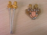
I've been measuring my dipole antenna impedance at UHF band recently,i used single-ended two-port VNA and calculated the final differential impedance by some formula directly from S11/S22/S12/S21. Attached(the coaxial one) is my differential probe made by coaxial cable.
Before measure the dipole,0603 100R resister is measured to verify and confirm the whole measurement method including the formula.And i calculated and got the impedance of 102.7+j2.5 Ohm,I believe it is good enough! Then i changed 100R resistor to my DUT,PCB dipole antenna.

BUT, the final calculated impedance is -4.6+j144.2 Ohm. The Imag part is very similar to my simulation value,the Real part is smaller to my simulation value which is about 19 Ohm,Also the Real part is negative! There must be sth.wrong!
I can not access anechoic chamber now and do the measurement in lab where has some reflections nearby. The curve on the VNA screen jitters a little when move the dipole antenna WASD. Is the anechoic chamber very important?or anything else wrong?


I need your help,thanks a lot!!
 

Attachments

  • IMAG0012a.jpg
    IMAG0012a.jpg
    97.4 KB · Views: 137

Hi,

I fear a problem similar to quantum mechanic ; it is not a joke !
The system under test (your RFID antenna) is disturbed by the the measurement system... I believe.
This test seems very difficult to give a good measurement.

Could you simulate your RFID antenna with 3D-EM software ?
Maybe, did you do...

BR
 

Another problem is the coax cables forming part of the antenna. Use a 1:1 transformer at the antenna terminals to reduce this effect.
 

Another problem is the coax cables forming part of the antenna. Use a 1:1 transformer at the antenna terminals to reduce this effect.

I have to use differential coaxial probe just because the 1:1 transformer could not be available,the reliability of measurement is very sensitive to the performance of transformer used. Could you pls,or anyone tell me one suitable transformer? thanks!

- - - Updated - - -

Hi,

I fear a problem similar to quantum mechanic ; it is not a joke !
The system under test (your RFID antenna) is disturbed by the the measurement system... I believe.
This test seems very difficult to give a good measurement.

Could you simulate your RFID antenna with 3D-EM software ?
Maybe, did you do...

BR

Only the antenna pattern is simulated by HFSS and got required performance such as impedance,return loss,gain,etc.
 

Measured negative real values, are mostly an operator error.
How was the calibration performed? By checking/calibrating your probe as open load and short are negative real values avoided in an passive antenna.
If it not is possible to do that kind of VNA calibration, make a coaxial balun for narrow band measurements. That kind of balun is very simple to calibrate/verify.
Can not see any ferrite tubes on the balun cables? It is a must to reduce coaxial cable effect on the antenna.
 

Measured negative real values, are mostly an operator error.
.

I've measured one resistor before connecting my antenna to verify the whole measurement system and found the result is correct, so i believe the calibration is good enough.

Coaxial balun,you mean which type? I've tried 1:4 coaxial balun with one half the wavelength, I need another method to do the measurement and double check the impedance. thanks.
 

Verifying with a resistor, is LOAD. How about OPEN and SHORT??
Evan a bad calibrated VNA do often show a nice dot in the center of Smith chart, and you can neither say anything about if electric delay is correct set.
Negative real values indicates a major calibration error. Before a correct calibration is done is a VNA an useless tool for you.
 

Verifying with a resistor, is LOAD. How about OPEN and SHORT??
QUOTE]

Yes,I did the full calibraion with OPEN/SHORT/LOAD,and then measure one resister just for verification before connecting my final DUT. The final impedance is calculated from S parameters.
I'll check and think it over,maybe somewhere is wrong,calibration steps will be carefully repeated again. thanks .

- - - Updated - - -

Verifying with a resistor, is LOAD. How about OPEN and SHORT??
QUOTE]

Yes,I did the full calibraion with OPEN/SHORT/LOAD,and then measure one resister just for verification before connecting my final DUT. The final impedance is calculated from S parameters.
I'll check and think it over,maybe somewhere is wrong,calibration steps will be carefully repeated again. thanks .
 

OK rf1008.
Now, could you describe your backround and boundary conditions of simulation HFFS ?
How do you made your exitation ? with coaxial ports shielded or not...

I think that you need to check the independance of your antenna.

BR
 

Status
Not open for further replies.

Part and Inventory Search

Welcome to EDABoard.com

Sponsor

Back
Top