Continue to Site

Welcome to EDAboard.com

Welcome to our site! EDAboard.com is an international Electronics Discussion Forum focused on EDA software, circuits, schematics, books, theory, papers, asic, pld, 8051, DSP, Network, RF, Analog Design, PCB, Service Manuals... and a whole lot more! To participate you need to register. Registration is free. Click here to register now.

[SOLVED] 8051 interrupt problem

Status
Not open for further replies.

ark5230

Advanced Member level 3
Joined
Jun 29, 2009
Messages
862
Helped
163
Reputation
324
Reaction score
140
Trophy points
1,323
Location
India
Activity points
6,187
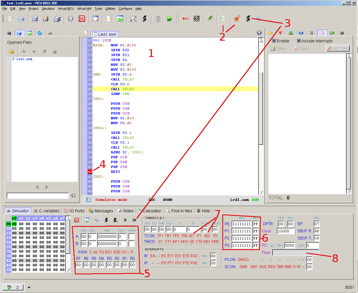
I am using 89s52 to test use of External Interrupt..

1. The main program blinks two LED's
2. On one interrupt 1 LED blinks and other goes off.
3. On the other interrupt second LED blinks and first one goes off.

The two LED's are on P0.0 and P0.1
Interrupt inputs are given to pins P3.2 and P3.3 using a push button.

All works well but after the control returns from interrupt, it takes some 20 seconds to resume the main program.
I am not able to understand what is going wrong.
Any suggestions will be of great help.
The code is as follows.

Code:
        ORG 0
        SJMP MAIN
        ORG 3
        LJMP ISR1
ORG 0BH
RETI

        ORG 13H
        LJMP ISR2
ORG 1BH
RETI
ORG 23H
RETI
ORG 2BH
RETI
ORG 30H
MAIN:   MOV P3,#255
        SETB EA
        SETB EX0
        SETB EX1
        MOV P0,#0
GEN:    MOV R2,#10
        MOV P3,#255
        CALL DELAY
        SETB P0.0
        SETB P0.1
        CALL DELAY
        CLR P0.0
        CLR P0.1
        SJMP GEN

ISR1:   MOV P0,#0
        CALL DELAY
        MOV P0,#0
        SETB P0.0
        CALL DELAY
        CLR P0.0
        DJNZ R2, ISR1
        RETI
ISR2:   MOV P0,#0
        CALL DELAY
        MOV P0,#0
        SETB P0.1
        CALL DELAY
        CLR P0.1
        DJNZ R2, ISR2
        RETI
DELAY:  
        MOV R3,#5
LP3:    MOV R4,#100
LP2:    MOV R5,#255
LP1:    DJNZ R5, LP1
        DJNZ R4, LP2
        DJNZ R3, LP3
        RET
        END
 
Last edited:

you are doing delay-clear-delay-set-loop of the LED pins in your main loop, and ALSO doing a set/reset of LEDs in your ISR's.
I suggest you do the initial blink before the main wait loop.

In addition, its not clear what is the purpose of R2 which is also used in both the main & the isr's ?
 
kripacharya
Thanks a lot for useful suggestions, it makes things more clear.
The purpose of R2 is to blink the LED only 10 times in the ISR (both).
The presence of R2 in main is used to update the value of R2=10 repeatedly in the main loop.
I agree there are other more efficient and effective ways of doing it, it was a stage in development.
It is interesting to note that the problem is caused by the alteration of the value held in accumulater by the ISR. When the Accumulator is pushed and popped in each ISR the problem is solved.

:-D
 

kripacharya

It is interesting to note that the problem is caused by the alteration of the value held in accumulater by the ISR. When the Accumulator is pushed and popped in each ISR the problem is solved.

:-D
Problem is caused R2=0H after the interrupt. Next interrupt will have the delay defined R2=FFH.
Code:
ORG 00H
	JMP MAIN
ORG 03H
	JMP ISR1
ORG 0BH
	RETI
ORG 13H
	JMP ISR2
ORG 1BH
	RETI
ORG 23H
	RETI
ORG 2BH
	RETI
ORG 100H
MAIN:	MOV P3,#255
        SETB EX0
        SETB EX1
        SETB EA
        MOV P0,#0
    	MOV P3,#255
GEN:    SETB P0.0
        CALL DELAY
        CLR P0.0
        CALL DELAY
        SJMP GEN
ISR1:
[COLOR="#FF0000"]        PUSH 05H
        PUSH 04H
        PUSH 03H
	MOV R2,#10[/COLOR]
        MOV P0,#0
ISR11:
	SETB P0.1
        CALL DELAY
        CLR P0.1
        CALL DELAY
        DJNZ R2, ISR11
[COLOR="#FF0000"]        POP 03H
        POP 04H
        POP 05H[/COLOR]
        RETI
ISR2:
[COLOR="#FF0000"]        PUSH 05H
        PUSH 04H
        PUSH 03H
	MOV R2,#10[/COLOR]
        MOV P0,#0
ISR21:
	SETB P0.2
        CALL DELAY
        CLR P0.2
        CALL DELAY
        DJNZ R2, ISR21
[COLOR="#FF0000"]        POP 03H
        POP 04H
        POP 05H[/COLOR]
        RETI
DELAY:
        MOV R3,#5
LP3:    MOV R4,#100
LP2:    MOV R5,#10
LP1:    DJNZ R5, LP1
        DJNZ R4, LP2
        DJNZ R3, LP3
        RET
END
 
Last edited:
Pplus
Thanks for the input. I am trying to understand this. It seems more plausible. If I do not get some point in this I will revert back to the post for clarification.
 

It is advisable in ISR's to routinely 'save' upon entry whatever register/flags is used within that ISR, and then 'unsave' them before exiting. Since iSR's can occur anywhere during main program execution and could inadvertently change a register/ flags value which is also being used in the main loop.
 
You have never used a simulator?
2086669600_1371709925.png

1 - Load your code.
2 - Compile or run simulator.
3 - Step or run.
4 - Set breakpoint.
5 - Watch registers.
6 - Watch ports.
7 - Invoke interrupt
8 - Elapsed time

More detail is in the manual to program.
 
Last edited:
Status
Not open for further replies.

Similar threads

Part and Inventory Search

Welcome to EDABoard.com

Sponsor

Back
Top