Continue to Site

Welcome to EDAboard.com

Welcome to our site! EDAboard.com is an international Electronics Discussion Forum focused on EDA software, circuits, schematics, books, theory, papers, asic, pld, 8051, DSP, Network, RF, Analog Design, PCB, Service Manuals... and a whole lot more! To participate you need to register. Registration is free. Click here to register now.

[SOLVED] 8 x 8 LED Matrix displays using HT1632 (Sure De-DP100's)

Status
Not open for further replies.
Tell you what mate, you have made me smile many thanks!! Hope you are well and family is well, I've spent *hours* over the last couple of days playing because the "New" 32x08 panels 2 weeks of waiting for, turn out to be different.. AND, I've ordered 3mm accidentally, the existing is 5mm!!! So, instead, we have 2 32x16 bi-color 5mm ones on order!!!
Disapointingly the "New" style sure LED panels don't have the nice scored break-off edges the old ones have. I have ground half an inch off the width on each side just upto a bit of track on the board but I can't edge them together like I'd hoped!!!

I've just video'd my 4 panels working and here it is.. You'll see the bottom right hand one is a bit larger! :) Silly me...

I am on the edge of the 16f723... Suggest an demoboard with SD on it we can both get one each if you can... If we buy the same thing, then at least we have easy codeswaps again and everything,...

There is something I want you to see in the "NezoltSoft" Bitmap-maker, skydrive again, you can load each line with a different font....

AND!!!!! :) I used the font editor to create a character set that in the capitals is all the top half of large capitals, the lower case letters are the bottom half of the massive capitals, so when done one line above the other, caps or not, we get a double height font!! :) Clive Sinclair (My hero for 30 years) would approve I hope.!
MSN me matey..
NEAL

---------- Post added at 20:35 ---------- Previous post was at 20:31 ----------

Here's 4 panels again...
 

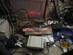
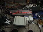
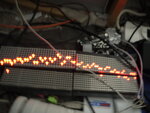
Using the same codebase, and several hours of overnight coding, I've managed to make an osciliscope using this setup!! 16dots x 32 isn't a lot and I've not worked out the maximum frequency yet, but I'm sure it'll get used! I'm just working on the triggering logic to get a steady wave display, I'm intending usig RA1 with a pot to set the triger level just for convienience.! I've not even put an opamp on the RA0 input yet so its just 0-5v, and a bit jittery, but plugged into my PC speakers I can see waves. I can see mains-hum if I just put my fingers on the pin!!
NEAL
 

P1000630.JPG
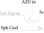
Superb!, with a pot "dragging the signal from a desk speaker towards 5v I can tune the dot to be in the middle... I've added a trigger that writes 64 samples when the A to D value has been below 30 an then back above 220.... If nothing is triggered for 1000 conversion loops it triggers just to give a line of nothiness... Tell you what, it might even be useful!!!

BiasDrive.jpg

P1000630.JPGP1000620.JPGP1000624.JPGP1000629.JPG
 

Take a look mate! My setup still is 3x3mm and 1x5mm.. I'm awaiting new soon...


---------- Post added at 18:36 ---------- Previous post was at 18:34 ----------


Hi!

I have bought a De-DP100 driver board and 3 LED panels. I have tested them with the software provided, and it works well!

Now I would be very interested in making my own code :)
I am experienced in programming, but the "how to communicate with an external microcontroller" part remains unclear...

I see you have done an awesome job, Neal!
I'd really like to learn from the code you wrote.

You told it could be downloaded at this address, but I don't see the zip files you are talking about. Is it normal?

Thanks in advance and keep on the good work!
 

Yes sorry, my code's going a major re-write at the moment and I'm trying to impliment some version control so I dont get mixed up!!!

Can you tell me which LED panels they are, there is a difference between new and old!!! Have you tried installing the firmware supplied by Sure's website, if the "De-DD2110" "NEW" code works or if their "OLD" one does.. The defference is in the commons, one is NMOS and other PMOS driven!!!

Look out for the different panels, I;ve got 1 old and 3 new, and have had to write a bit of a jiggle to get round it....
I'll re-post a zip when I know which panels you've got!

Kind regards! :)
NEAL
 
I got the old ones! (those with HT1632, not HT1632C)

EDIT : DE-DP104

Actually, I have no idea how to use the codes given by Sure Electronics. :lol:
I understand them, but I don't know how to transfer them to the chip (I have downloaded MPLAB but I am still stuck).

In fact, I do not think I need your whole script.
When I can manage to light up any LED I want on the panels, I think I can do the rest by myself!
 
right then matey, look in
https://dub110.mail.live.com/defaul...c8d&sc=documents&uc=1&id=E997A0EACCD4CC8D!220

at V15... Its setup for 4 old panels, 2 on BR1 as cs1&2 and 2 on BR2 as CS1&2 (5&6 in the code)

Regards,
Let me know how you get on bud..! :)
NEAL

---------- Post added at 16:51 ---------- Previous post was at 16:50 ----------

[q]
PORTB=0;;
CLK=(1);
DAT=(1);

ht1632_sendcmd(HT1632_CMD_COMS00); // LEDs on
ht1632_sendcmd(HT1632_CMD_MSTMD); // Master Mode//
ht1632_sendcmd(HT1632_CMD_SYSON); // System On
ht1632_sendcmd(HT1632_CMD_LEDON); // LEDs on
ht1632_sendcmd(HT1632_CMD_BLON); // LEDs on
[/q]

this is the bit to alter for "New" panels, the new ones take COMS10 instead!!!
NEAL

---------- Post added at 16:56 ---------- Previous post was at 16:51 ----------

my ICD2 connected straight to the DemoBoard by soldering a header on and using the standard telephone-connector lead... I love MPLAB!!!
L0
 
Thanks a lot!

Actually, I got no ICD... I am using the micro USB port onboard.
Can I still run your code?

I'm an absolute newbie with MPLAB.
If I open MultiLEDDisplays.mcp and then just build, it is supposed to work?
 

Afraid not matey, this is code for uploading onto the board using a programmer and the ICD connector on the board... I started playing with these when I discovered there is no pound sign in their supplied boardcode....

I can recommened getting the programming kit of your looking at this as a project to play with... I've found the board very usedful for a few things because it gives you access to a lot of the the chips i/o on the breakouts. The 3 Analoge ports, all of PORTB and a bit of PortC are easily hookable too, and of course the USB serial interface too which I've just used to make my board display data from an Access mdb Database in a choice of font on a multi-color screen today.!!!
https://www.edaboard.com/threads/221384/#post942019


Regards
NEAL
 

Ok thanks.

What I would like to do is a real time communcation with the PC, that decides which LED must be light up or not.
Is such a program feasible?
 

The PC Programming bit is not likely to give nice results.... You can delve into the old dos font t get lines and squares and stuff but the only way I can tell you to switch on a dot with the supplied firmware is to type a fullstop I'm afraid...

ICD's are easily available, gwan, dig in!!!
:)
NEAL
 

Take a look mate! My setup still is 3x3mm and 1x5mm.. I'm awaiting new soon...

Very impressive, you've taken your project a long way since I last took a look.

Have you figured out what your next PIC will be after you migrate from the 16F723?

BigDog
 

Thanks bigdog :) I hope all is well in your bit of the world, Greeetings from the "East Midlands"! :p

I have appreciated your input on things, "so what would you suggest" would be my 1st question... I've seen PIC18/24/32 demoboards on ebay that look inviting, ! I consider you a serious guru so I will follow any suggestions.... I think a wireless-web-server based board would be ideal next.. Or at least ethernet.. Have you any kit like that you can get me started with? :)

BUT!!! I have just had an old Laserjet HP literally just turn up at my house for scrappage... Motors/driver IC's, bearings and shafts etc are always useful, but, hopefully (As all "Laserjet 5 era" printers,and a lot of old Cisco Routers, it will have in it a 680x0's in!!!!! I would love to "Move back home".

I learned to properly code by getting into the Demo circuit on the 68000 Atari ST about 20 years ago. Demo sources for MOD musicplayers, scrollers, 3d etc were my choice of "Pulbic Domain" rewards for sending my demos in. I bought HiSoft DevPak registered) Graphics coding has been a good lesson in lots of things, hardware, binary maths, bitplanes, masks, matrices, etc)
I've been writing and dissasembling 680x0 code from the age of 15 (removing protection from games, the "Laserburn" on Rampage (atari ST ~1990) so I still feel its my "prefered" language and would happily look at the printers code to get me started.. The ST did have a lot of helping hardware, VBL & HBL interupts, Blitter (STe) and things, but I might not get that far... An easier way would be an old 2600 router. There was a "forum competition" somewhere once I missed based around reprogramming cisco kit for interesting things, the bootloader and massive onboard resources would make an old 2500 "perfect" for that sort of thing... !

Neal

---------- Post added at 22:11 ---------- Previous post was at 22:08 ----------

ps I'm just integrating the Robot-car and the "Display panel" genres... The robot's going to be able to tell it it loves you after in bumps into you... :)

Neal
 

I have appreciated your input on things, "so what would you suggest" would be my 1st question... I've seen PIC18/24/32 demoboards on ebay that look inviting, ! I consider you a serious guru so I will follow any suggestions.... I think a wireless-web-server based board would be ideal next.. Or at least ethernet.. Have you any kit like that you can get me started with? :)

I have numerous evaluation/development kits. If you like Microchip PIC and would like to stay with that architecture, I would recommend either a PIC24 or PIC32 based development board.

I'm partial to buying Microchip dev boards, they are well documented and of high quality.

I have several of the following:

**broken link removed**

**broken link removed**

**broken link removed**

**broken link removed**

That being said, I been buying FPGA dev boards from Digilent for years and they have started to sell some incredible PIC32 based dev board:


One of the reasons I really like both these companies dev boards is they are easily expandable with plugin modules. Microchip has the PICtail Plus modules and Digilent has the PMODs. If you want to develop a wireless app, no problem, just plug a wireless module into the dev board.

Digilent's chipKIT's while they do not share that feature, offer a lot of bang for the buck, especially for a PIC32 dev board.

BigDog
 
PIC24 kit is now running my displays!! No thoughts of its WiFi module yet, just happy to have results!! An issue of it being 3v hasn't affected anything thankfully!
:)
NEAL
 

Status
Not open for further replies.

Part and Inventory Search

Welcome to EDABoard.com

Sponsor

Back
Top