Continue to Site

Welcome to EDAboard.com

Welcome to our site! EDAboard.com is an international Electronics Discussion Forum focused on EDA software, circuits, schematics, books, theory, papers, asic, pld, 8051, DSP, Network, RF, Analog Design, PCB, Service Manuals... and a whole lot more! To participate you need to register. Registration is free. Click here to register now.

8-bit Binary Counter Assignment

Status
Not open for further replies.

Eicalos

Newbie level 5
Joined
Dec 16, 2011
Messages
9
Helped
0
Reputation
0
Reaction score
0
Trophy points
1,281
Activity points
1,341
I have the assignment.

Design Schematic with Quartus II

a) 1-bit Binary Adder (Full Adder) use AND2/OR2/INV and create symbol (Schematic Symbol) name "FA"

b) 8-bit Binary Adder use Full Adder from a) create (Schematic Symbol) name "ADD8"

c) 8-bit Register use D-Type Flip-Flop create Schematic Symbol) name "REG8"

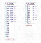
d) 8-bit Binary Counter use symbol from b) and c)


a,b,c. I can did it. But d I don't know how to integrate it.

Plz help me!!!
pic.JPG
 

How to do it?

The way is show in the figure on page 2.

I did n't get your question?
 

quite simple.

Connect all the A inputs to the Q output of the register.
Connect B0 input to '1' and all of the rest to '0' (including CIN)
Connect the sum outputs to the D inputs of the register
connect a clock and away goes your counter.

all seems a faff - in VHDL this whole thing can be written as:

Code:
process(clk)
begin
  if rising_edge(clk) then
    counter <= counter + 1;
  end if;
end process;
 
How to do it?

The way is show in the figure on page 2.

I did n't get your question?

In my diagram have 2 device. I want to known how do I connect 2 device in order to get circuit diagram this.

65900d1324297153t-pic2.jpg
 

In schematic diagram I do it successful. But the continue assignment, Write all of them into VHDL code. I can write 8-bit Register this follow

library ieee;
use ieee.std_logic_1164.all;
use ieee.std_logic_arith.all;

entity REG8 is --Initiate 8-bit register
generic( USE_CLK_LEVEL : std_logic:='1'; -- Edge clock
n : integer :=8 -- 8-bit
);
port( CLK: in std_logic;
D : in std_logic_vector(n-1 downto 0);
Q : out std_logic_vector(n-1 downto 0)
);
end REG8;

architecture behave of REG8 is
begin
process (CLK)
begin
if CLK'event and CLK = USE_CLK_LEVEL then
Q <= D;
end if;
end process;
end behave;

But 8-bit adder I cannot write it. Plz help me and I have some question how do I use two code of them (8-bit Register and 8-bit Adder) convert to 8-bit binary counter. This follow

untitled.JPG
 

Attachments

  • untitled.bmp
    595.2 KB · Views: 89
Last edited:

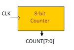
how about this code. It does everything you're asking in hardly any VHDL code in 25 lines, an allows you to specify the counter width without a generic (by setting the size of the count port externally)
Code:
library ieee;
use ieee.std_logic_1164.all;
use ieee.numeric_std.all;

entity counter is
  port (
    clk   : in  std_logic;
    count : out unsigned
  );

end entity counter;
  
architecture rtl of counter is
  signal cnt_tmp : unsigned(count'range) := (others => '0');
begin
  
  process(clk)
  begin
    if rising_edge(clk) then
      cnt_tmp <= cnt_temp + 1;
    end if;
  end process;
  
  count <= cnt_tmp;
end architecture;
 

Status
Not open for further replies.

Part and Inventory Search

Welcome to EDABoard.com

Sponsor

Back
Top