Continue to Site

Welcome to EDAboard.com

Welcome to our site! EDAboard.com is an international Electronics Discussion Forum focused on EDA software, circuits, schematics, books, theory, papers, asic, pld, 8051, DSP, Network, RF, Analog Design, PCB, Service Manuals... and a whole lot more! To participate you need to register. Registration is free. Click here to register now.

7kW charger for automotive use (230VAC mains three phase input)?

Status
Not open for further replies.
T

treez

Guest
Hello,
A friend has been asked to go for an interview for the design of a 7kW automotive battery charger

https://www.zap-map.com/charge-points/basics/

..I said that the topology to do this would be seven phase-shift-full-bridge converters in parallel. These would have as their input, the 380VDC output of seven paralleled, interleaved, CCM Boost PFC stages. Their would be cooling fans to cool it all.
Is this topology arrangement correct, or even likely?
 

Thanks,
Surely you would not use a three phase rectifier?
That gives an output of some 600VDC...which will surely mean too much switching loss in the phase shift full bridge converters.
 

I don't see a problem with 600V or so out of the PFC stage, for this were IGBTs developed, motor drives do this sort of thing all the time.

Actually, were I doing this, I would be reaching for the old school, crude but very reliable way, weight not being an issue in something wired to a 7KW three phase line....
One delta - Y transformer and one Y-Y transformer setup to give the same phase to phase output voltages, and two three phase bridges, gives you 12 pulse rectification and very low ripple even without ANY bulk bus cap, possibly use a saturatable reactor to set the charging current (Or possibly just a really butch tapped inductor or deliberate leakage inductance, 1950s tech but not uncommon in forklift truck chargers (Which get abused in all sorts of stupid ways) and VERY reliable).

Actually a canny modern approach would be to make 3 converters where the output current tracked the input voltage (effectively butch isolated PFC boards) and just common the outputs, sure there will be plenty of 300Hz ripple, but does the battery care and it does away with the bus caps.

Plenty of interesting ways to skin this cat, and plenty of interesting design tradeoffs to discuss at interview, personally I would much rather have an interviewee asking probing questions and exploring the solution space then have one turn up with a fixed idea about how to solve something.

I am not sure that 7 wimpy little 1KW modules is the way to go however, 3 modules seems more reasonable, and once away from the front end some other combination might make sense.

Regards, Dan.
 
  • Like
Reactions: treez

    T

    Points: 2
    Helpful Answer Positive Rating
the 6phase, 12 pulse rectifier is, as you know, not power factor corrected though.
 

Sounds too specific when the battery and specs are unspecified.

Multiphase certainly reduces the inductive losses by sharing interleaved current pulses, and many have more than 5 phases in DC-DC converters but these are running much higher than line rates

Given the power range of 7kW is typical for automotive generators that are generally 3 phase full bridge which causes a lot stress on each diode but the more phases, the less ripple.

For mains chargers at 50Hz, the key factor is phase harmonic current when balanced with balanced charge pulses on each phase, the neutral current can exceed the in-phase current by root3.

The 1st part of the design to actually write the specs.
The 2nd part is to examine all the topologies for tradeoffs for active PFC , forward converters and multi-phase options that split up the load into different phases.
The 3rd part is to review the designs choose the two best approaches and then test them against the specs and review the design again with peers.

The actual choice doesn't matter.
It's the design motus operandi that counts for me.

The 7 phase PFC forward FB converter from a 3 phase line might work, but would it be the best design?
 
  • Like
Reactions: treez

    T

    Points: 2
    Helpful Answer Positive Rating
I would design a standard single phase building block of perhaps 1Kw to 1.5Kw that can be slaved to other identical building blocks to provide power levels in multiple steps, from one to three phases.

This might offer some redundancy, and would be attractive from a manufacturing point of view, the servicing point of view, as well as having some attributes for the sales and marketing people possibly being able to offer a future upgrade path.

If going for an interview for a purely technical design position, some awareness of other aspects of the (team) project will certainly not go against you.
 
  • Like
Reactions: treez

    T

    Points: 2
    Helpful Answer Positive Rating
Splitting the 7 KW into seven 1KW sections does mean that the wiring can be a lot smaller, i.e. you can take most of the mains feed down PCB tracks. Having N pluggable modules into a mother board, does improve down time as modules can be replaced. The mother board could be populated for say 20 modules (with a spare one clipped inside the lid?). If there were a few LEDs on the modules, then an unskilled opo could interchange boards and send the faulty board back to the OEM for repair. From an engineering point its a no brainer, but for the sales manager it will be a no no as its will be more expensive then a single unit solution.
Frank
 
  • Like
Reactions: treez

    T

    Points: 2
    Helpful Answer Positive Rating
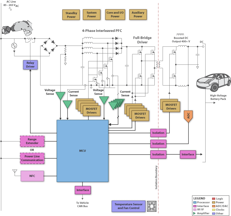
Yes I am pretty sure the solution is CCM Boost PFC followed by phase shift full bridge. Its just a matter of how many of them in parallel.
 

6369.gif

TI prefers 4 Phases PFC for optimal ripple cancellation for EV chargers with only single Phase Full Bridge forward conversion with synchronous secondary regulation for ganged operation and external multi-phase interleaved sync. This is their general solution for Electric Vehicle (EV) charging stations for both Level 1 & 2.
 
  • Like
Reactions: Mr.Cool and treez

    T

    Points: 2
    Helpful Answer Positive Rating

    Mr.Cool

    Points: 2
    Helpful Answer Positive Rating
Wow, Thankyou!, I am guessing that there are multiple cells in the battery, and that there will be a charger for each cell, so many many chargers switching off the full bridge output.?
 

Wow, Thankyou!, I am guessing that there are multiple cells in the battery, and that there will be a charger for each cell, so many many chargers switching off the full bridge output.?

only 1 charger
 
  • Like
Reactions: treez

    T

    Points: 2
    Helpful Answer Positive Rating
From an engineering point its a no brainer, but for the sales manager it will be a no no as its will be more expensive then a single unit solution.
Frank
It may not be, if you take the whole business cycle into account.

If you have ever worked in a production environment, or in parts procurement, or the servicing department, or training, or warehousing and distribution, its always easier where there are a lot of identical units, rather than having fifteen different variants of the same thing.
 
  • Like
Reactions: treez

    T

    Points: 2
    Helpful Answer Positive Rating
7 kW is a 3 phase input, we routinely design these with just a 6 diode bridge on the front end, and 10uF of film cap 700V, then a 100kHz PWM phase shift full bridge to do the down conversion, 900V mosfets or now SiC 1200V, they only switch 14A, 2 x planar Tx's to give the 7kW out, current doubler out for high currents...
 
7 kW is a 3 phase input, we routinely design these with just a 6 diode bridge on the front end, and 10uF of film cap 700V, then a 100kHz PWM phase shift full bridge to do the down conversion, 900V mosfets or now SiC 1200V, they only switch 14A, 2 x planar Tx's to give the 7kW out, current doubler out for high currents...

thanks, ..no PFC?....just one phase shift full bridge converter for 7kw? Why "two" planar transformers?
 

thanks, ..no PFC?....just one phase shift full bridge converter for 7kw?
With 10 µF bus capacitor the converter can be operated as a buck PFC.
 
  • Like
Reactions: treez

    T

    Points: 2
    Helpful Answer Positive Rating
Thanks, but I don't think you can have PFC downstream of a 3 phase rectifier?
Please see ltspice simulation of 3 phase rectifier with purely resistive load......there is no pfc.
 

Attachments

  • Three phase rectifier.txt
    2.3 KB · Views: 93

I don't think you can have PFC downstream of a 3 phase rectifier?
Right, just a certain PF improvement compared to a bus with large capacitor.
 
  • Like
Reactions: treez

    T

    Points: 2
    Helpful Answer Positive Rating
With 7KW of power flowing, surely we need full PFC?

By the way, does anyone know why the phase currents are not the same in waveform shape in the 3 phase rectifier simulation of post #17?
 

The circuit achieves PF pf 0.96, but harmonic currents are above IEC 1010 limits.

- - - Updated - - -

By the way, does anyone know why the phase currents are not the same in waveform shape in the 3 phase rectifier simulation of post #17?
A problem of your series connected voltage sources. Use phi = 0, 120, 240 degree instead.

- - - Updated - - -

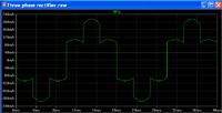
Phase current should look like this

 
  • Like
Reactions: treez

    T

    Points: 2
    Helpful Answer Positive Rating
Status
Not open for further replies.

Part and Inventory Search

Welcome to EDABoard.com

Sponsor

Back
Top