Continue to Site

Welcome to EDAboard.com

Welcome to our site! EDAboard.com is an international Electronics Discussion Forum focused on EDA software, circuits, schematics, books, theory, papers, asic, pld, 8051, DSP, Network, RF, Analog Design, PCB, Service Manuals... and a whole lot more! To participate you need to register. Registration is free. Click here to register now.

7805 Voltage regulator????

Status
Not open for further replies.

Elimathew

Member level 5
Joined
Jun 21, 2011
Messages
88
Helped
2
Reputation
4
Reaction score
2
Trophy points
1,288
Location
India
Activity points
1,894
hey i have 9v power supply and i need 5V output voltage im using 7805 can anyone tell me what should the circuit be like
 

The schematic is shown in the first page of the datasheet (fixed voltage regulator)
**broken link removed**

It is basically like
**broken link removed**

and the pinout is
**broken link removed**

Alex
 

hello,
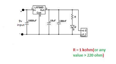
Here is the Circuit which i have used in number of projects :
12.jpg

Good Luck :)
 

The circuits shown above are basically what you have to use. If the 9v input is to be placed far away from the 7805, I would also add a 10uF capacitor. Anyways, the circuit is simple enough. So, good luck.

Hope this helps.
Tahmid.
 

hey i am using a DC supply so is there any need of capacitors

---------- Post added at 19:01 ---------- Previous post was at 18:58 ----------

"If the 9v input is to be placed far away from the 7805"what does far away mean exactly
 

yes jayant you are right !!! i did not saw that .. i just googled it and downloaded . . and posted it here for reference :)

@Eli - Capacitor is required as inside the regulator is a high gain amplifier, always monitoring the difference in output voltage with an internal reference supply. Like most amplifiers, it can become unstable if variations in supply voltage cause a change in output voltage. Given the battery has quite a high internal resistance, it is very likely it's voltage will vary if the load changes..
You should always connect a capacitor preferably in the region of 10uf to 1000uF across the input terminal and ground with the wiring as short as possible(usually i go for 1000u:twisted:f ). A capacitor on the output is less important but it is preferable to have one close to the output and ground pins as well. If you make the output capacitor too big, it has a detrimental effect on the regulators transient response. .

----------------------------------------------------------------------------------------------
errata:
Reverse the polarity of led in the image : images.jpg
Good Luck :)
 
Haha . . u have placed resistance above led.. :-D
remind me of something>>> remember current limiting resistance placement(@Tahmid) .. :twisted:
 
Last edited:

Haha . . u have placed resistance above led.. :-D
remind me of something>>> remember current limiting resistance placement(@Tahmid) .. :twisted:

And the problem is?

---------- Post added at 22:28 ---------- Previous post was at 22:27 ----------

You can place it before or after the LED, doesn't matter.
 

No there is no problem .. :D
just reminded me of that post !!!
 

yes he can use any value of resistance greater than 220ohm ..
value of R is related with glow of led.. lower the value of R brighter the glow. .
 

Let's calculate. The output is 5v. If we have a RED LED, it has Vf = ~1.4v . Maximum current through it can be taken as 20mA. 10mA is a good amount of current to pass through it for decent light level. So, value of R required is, (5-1.4)/0.01 = 360 ohm

The minimum resistance has been said to be 220 ohms. With RED LED, the maximum current passing is (5-1.4)/220 = 16mA
With GREEN LED or LEDs of other colours, the current passing will be lower since they have a higher Vf.

Hope this helps.
Tahmid.
 

@ Tahmid-- yes you are right!!
@cameo -- you can use any value upto 10k(360.. 450.. 750.. 1k ..2.2 k so on) .. You can go beyond this value(10k) but the glow will be very dim!!!
Actually that depends how much light level do you want .. the higher the resistance the lower will be current and it will glow dim!!!
Even you can use 33ohm with green blue and white led's But the current will be high and practically you can observe resistance getting hot. .
 

Actually i already had tried this value .. that is why i said that.. :D
What would you say i had tried 10 ohm too.. :twisted:
red,orange,infrared led will definitely get damaged (i tried that too :twisted:)
Try these resistances !!! :)
if you want me to post some pics, i can post them too!!! :p
I did not tried 1 ohm though. . :?: (m gonna buy one and try it asap) :twisted:

Good Luck :)
 

@ Tahmid-- yes you are right!!
@cameo -- you can use any value upto 10k(360.. 450.. 750.. 1k ..2.2 k so on) .. the higher the resistance the lower will be current and it will glow dim!!!

I think you didn't get my question right. and yes, I know ohms law.

there was a statement in one of the previous posts, "any value > 220 ohms". I was literally reffering to that, as any value > 220 ohms can go upto certain Mega Ohms upto insulation.
will your LED glow still?
 

Status
Not open for further replies.

Similar threads

Part and Inventory Search

Welcome to EDABoard.com

Sponsor

Back
Top