Arrowspace
Banned
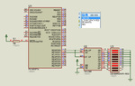
Can anyone verify my circuit. It's not working
Follow along with the video below to see how to install our site as a web app on your home screen.
Note: This feature may not be available in some browsers.
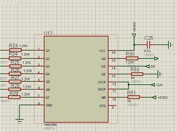
You can't tie SH_CP and ST_CP together.
Data is shifted on the positive-going transitions of the shift register clock input (SHCP).
The data in each register is transferred to the storage register on a positive-going
transition of the storage register clock input (STCP). If both clocks are connected together,
the shift register will always be one clock pulse ahead of the storage register.
From the datasheet:
Please be more specific and specify - what exactly doesn't work?
And what were your debugging efforts so far?
Did you inspect the soldering?
Did you try changing the component?
Do you see a clock signal?
Is the VCC correct and stable?
Did you verify data is coming in the DS pin?
Do you have an Oscilloscope??
int i=0;

unsigned int buf = 0b01010101;

void main()
{

direction();


while(1)
{

for(i=0;i<=9;i++)
{
   if ( (buf & 0x01) == 0)    //check bit 0
{
LATBbits.LATB0 = 0;
buf>=1;
}

else
{
LATBbits.LATB0 = 1;
buf>=1;
}
LATAbits.LATA4  = 1;        //  clock
   delay_ms(10);
LATAbits.LATA4  = 0;        //  clock
 delay_ms(10);

}
 delay_ms(250);
}
}You are not reloading the buf variable after the first loop.
Moreover, what exactly do you exect with this buf>=1 command ?
Hi
I don't know which Compiler you are using and which PIC you are using. I have written a code for you using mikroC PRO PIC Compiler just to show that it works. If you mention which compiler, PIC and what frequency crystal you are using then I will try to make a project for you using that compiler.
In the attached file there are two Proteus simulation files. One using LED and another using Relays. Test both with the same .hex file. I have used PIC16F877A with 4 MHz crystal.
I don't see any data chattering when SH_CP and ST_CP of 74HC595 is tied together. The LEDs and Relays turn on without any problem.
After you mention your compiler, PIC and crystal freq, I will make a project for you so that you can quickly test it in hardware using relays.
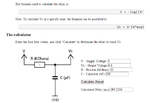
In the Relay based simulation file the capacitors at the base of the transistors are important. It gives delayed turn ON for relays. I think a 100 ms to 200 ms delay is enough and it will make Relays operate normally when data is shifted to 74HC595.
Anyway, quickly test my simulations and reply.

Here is the Schematic in PDF format.
We both have used same circuit , then why my circuit is not working.