Continue to Site

Welcome to EDAboard.com

Welcome to our site! EDAboard.com is an international Electronics Discussion Forum focused on EDA software, circuits, schematics, books, theory, papers, asic, pld, 8051, DSP, Network, RF, Analog Design, PCB, Service Manuals... and a whole lot more! To participate you need to register. Registration is free. Click here to register now.

74F74 Divider Phase shifter

Status
Not open for further replies.

neazoi

Advanced Member level 6
Joined
Jan 5, 2008
Messages
4,119
Helped
13
Reputation
26
Reaction score
15
Trophy points
1,318
Location
Greece
Activity points
36,918
74f74

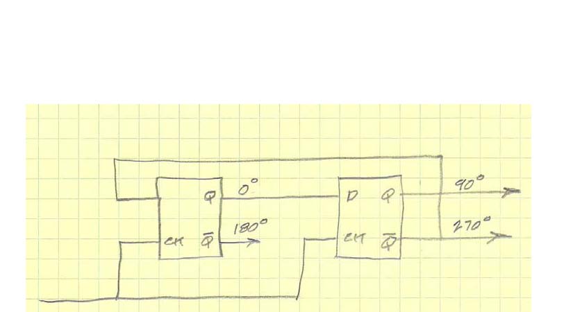
Hello I need to make a quadrature phase shifter (0, 90, 180, 270) and frequency divider using 74F74 flip flop.
I know how to achieve it using CD4013 but the 74F74 has also a set and clear pins.
Should I connect them to ground or to vcc if I want them not to affect its operation?
 

74f74 +divider

neazoi,
Unused set and clear inputs should always be tied to the inactive state to avoid inadvertent changes of state due to noise. In the case of the 74F74, the set and clear inputs are active low, so they should be tied to the "1" state. Tying them to Vcc will work. A more versatile solution is to tie them to Vcc through a resistor. In this configuration, you can short them to ground to force a given state for troubleshooting purposes.
Regards,
Kral
 
  • Like
Reactions: neazoi

    neazoi

    Points: 2
    Helpful Answer Positive Rating
Thank you,
Then I just disable them by deactivate them (connect them to vcc) and then the flip flob will operate like the cd4013
 

neazoi,
The 74F74 will operate similarly to the Cd4013, except that the set and clear inputs of the 4013 are active high, so the CD4013 set and clear inputs should be connected to ground if they are not used.
Regards,
Kral
 
  • Like
Reactions: neazoi

    neazoi

    Points: 2
    Helpful Answer Positive Rating
neazoi,
The 74F74 will operate similarly to the Cd4013, except that the set and clear inputs of the 4013 are active high, so the CD4013 set and clear inputs should be connected to ground if they are not used.
Regards,
Kral

Can some one please Explain the working and circuit of this
 
  • Like
Reactions: neazoi

    neazoi

    Points: 2
    Helpful Answer Positive Rating
The set and clear inputs force the output of the flip-flop to a known state. If the set input is active, the device will go to and remain in the "1" state. Similarly, if the clear input is active, the device will go to and remain in the "0" state. In both cases, the clock will have no effect on the output. If you don't want to force the device to a known, fixed state, then the set and clear inputs must be set to the inactive state. In the case of the 74F74, this means connecting them to Vcc. In the case of the CD4013, this means connecting them to ground.

I would like to know how this Ic would generate 90,180,270 degrees of phase shift I mean the circuits working
not the working of preset and clear pins.
 
  • Like
Reactions: neazoi

    neazoi

    Points: 2
    Helpful Answer Positive Rating
The set and clear inputs force the output of the flip-flop to a known state. If the set input is active, the device will go to and remain in the "1" state. Similarly, if the clear input is active, the device will go to and remain in the "0" state. In both cases, the clock will have no effect on the output. If you don't want to force the device to a known, fixed state, then the set and clear inputs must be set to the inactive state. In the case of the 74F74, this means connecting them to Vcc. In the case of the CD4013, this means connecting them to ground.

The chip logic generates too many harmonics. I wonder if a low pass filter at the output can eliminate them so you get a clear square wave on the oscilloscope...
 

??? If you filter the harmonics you WONT get a square wave!

Can you explain why you need the quadrature phases, it might help us to advise on a better way to produce them or a solution to the flip-flop method.

Brian.
 

??? If you filter the harmonics you WONT get a square wave!

Can you explain why you need the quadrature phases, it might help us to advise on a better way to produce them or a solution to the flip-flop method.

Brian.

I thought so...

I need to split an incomming RF signal into four phases in order to be used in quadrature mixers. Two 90deg phases would be though.
 

What kind of mixers are they and are they working at a single frequency or are they fed from a tunable oscillator source?

It may be easier than you think, don't forget that 0 and 180 degrees are the same signal inverted and so are 90 and 270 degrees, you may only need one 90 degree shifter and two inverters.

Brian.

If a single frequency were to be used it could be done with a rc or lc network. The problem is when working on broadband equipment where broadband oscillators are to be used. the flip flop is a good solution to this as it is broadband, provided that works withing it's max frequency limits but it has two disadvantages. The waveform is square (which is not as good as sine for this purpose) and you need a multiple of the input frequency to get divided out of phase signals.
Whereas the IF signals can be processed with dsp computer software easily the local oscillator phasing problem remains complicated when talking about broadband equipment.


the f4f74 can provide up to 30mhz in 4 phases with this, since it's input limit is 120mhz. As I said earlies the basic problem is to have an oscillator running from 4-120mhz to get 1-30mhz out. Unless you use a dds with shifted outputs it is difficult to maintain stability.

An idea would be to use the harmonics of an HF oscillator and filter the fundamental with a really good filter but again stability would be an issue on harmonics.

where can we apply input here.
when my input does not change synchronously with clock then how can we say that o/p of first flip flop is having 0 degrr phase shift.
please answer this question is bugging me from few days
 

Input is at the clock pins of the flip-flops.
Don't think of the 0 degrees point as being referenced to the input, it is the basis for the other three phase outputs.

Brian.
 

Betwixt is correct. I should have provided an explanation. This circuit is generating a 4 phase output that is derived from the clock input, which must be 4X the desired frequency of the output. You can consider any of the phases as the 0 deg phase. The other phases will be with respect to the selected 0 deg phase.You can use the direct clear inputs to initialize the counter to any desired state.
 

Status
Not open for further replies.

Similar threads

Part and Inventory Search

Welcome to EDABoard.com

Sponsor

Back
Top