Continue to Site

Welcome to EDAboard.com

Welcome to our site! EDAboard.com is an international Electronics Discussion Forum focused on EDA software, circuits, schematics, books, theory, papers, asic, pld, 8051, DSP, Network, RF, Analog Design, PCB, Service Manuals... and a whole lot more! To participate you need to register. Registration is free. Click here to register now.

7 segment display logic gate circuit

Status
Not open for further replies.

duxbuz

Newbie level 6
Joined
Feb 27, 2014
Messages
13
Helped
0
Reputation
0
Reaction score
0
Trophy points
1
Activity points
107
Hi

I am looking to use a 7 segment display triggered and am unsure of the circuit to run it.

I want to be able to create the circuits using gates in a logic sim.

I initially thought I would use a decoder of sorts, but have since noticed that they only provide one output per permutation of input bits, so I can only have one segment triggered at one time.

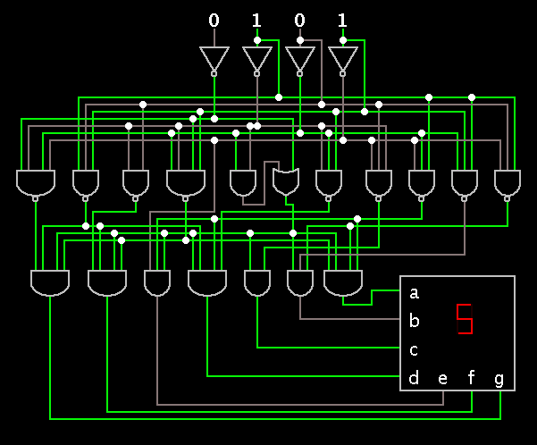
But then I came across a bcd to 7 segment decoder, which does what I want, so I am looking to create a circuit of gates with this functionality, I have seen some examples that i can use.

I also saw somewhere else this 4511 bcd to 7 segment decoder, which seems to be more than just a decoder. It has a latch.

My question is what is the best way to do this sort of logic circuit?

Is it to try and do it with a latch like a 4511, or just using another example of a bcd to 7 segment decoder?

Or is there another way that doesnt use a decoder?

Which is the best way with logic circuits?

Thanks
 

Try to do with decoder that works just fine
thanks
 

Since you mention the 4511, another useful IC is the 4543.

These accept a 4-bit input, and drive a 7-segment display.

A single IC can be multiplexed to display multiple digits.

There are differences between the 4511 and 4543. One might perform better for your needs than the other. These are the CMOS chips which run on a wide range of supply V.

There are also versions which run on 5V only.
 

Thanks for answers

Trying to just stick to logic gates with no ICs

Will keep that in mind for future reference though cheers
 

If you wish to use logic gates only, then you might like to consult this schematic showing how an IC does it (internally).


    V

    Points: 2
    Helpful Answer Positive Rating
Great thanks

- - - Updated - - -

If you wish to use logic gates only, then you might like to consult this schematic showing how an IC does it (internally).


Out of curiosity where did you get the schematic ? Is this from an ic or is it one of your own circuits
 

Falstad's interactive simulator has this circuit in its library, ready made.

You click the input wires at the top, and the display shows the decimal digit. Wires turn color to show what volt level they are at.

The link below will open the website www.falstad.com/circuit...
Load the schematic...
And run it on your own computer.
(Click Allow if a message appears asking to load the applet.)

https://www.falstad.com/circuit/e-7segdecoder.html
 

Go through this datasheet
 

Attachments

  • sdls111.pdf
    586.1 KB · Views: 97

Ok Cheers. I think I have this one already.

I am still having few issues getting it to perform correctly.

The '47' and the '48'. But I will just double check everything.

Thanks again.

- - - Updated - - -

Falstad's interactive simulator has this circuit in its library, ready made.

You click the input wires at the top, and the display shows the decimal digit. Wires turn color to show what volt level they are at.

The link below will open the website www.falstad.com/circuit...
Load the schematic...
And run it on your own computer.
(Click Allow if a message appears asking to load the applet.)

https://www.falstad.com/circuit/e-7segdecoder.html

This is great!
 
Last edited:

Status
Not open for further replies.

Part and Inventory Search

Welcome to EDABoard.com

Sponsor

Back
Top