Continue to Site

Welcome to EDAboard.com

Welcome to our site! EDAboard.com is an international Electronics Discussion Forum focused on EDA software, circuits, schematics, books, theory, papers, asic, pld, 8051, DSP, Network, RF, Analog Design, PCB, Service Manuals... and a whole lot more! To participate you need to register. Registration is free. Click here to register now.

7 segment and Microcontroller

Status
Not open for further replies.

AliRazoR

Advanced Member level 4
Joined
Oct 26, 2010
Messages
115
Helped
4
Reputation
8
Reaction score
4
Trophy points
1,298
Activity points
2,001
Hi,

I want to drive 4 seven segment with IC 74HC4511, Do i have to put for each seven segment One of these IC's or one Is enough.(each seven segment shows different number)


thanks in advance
 

so, for each seven segment 1 74HC4511 is required.
 
  • Like
Reactions: kkcake

    kkcake

    Points: 2
    Helpful Answer Positive Rating
yes you need to connect
 
or you can use microcontroller for multiplexing
 

i am using pic 16f877 but because i do not have enough empty pin ,i am using 74hc4511 for each seven segment.

---------- Post added at 18:35 ---------- Previous post was at 18:33 ----------

i have another question:do you know how can i use multiplexer in Proteus?

---------- Post added at 18:35 ---------- Previous post was at 18:35 ----------

https://www.edaboard.com/threads/195090/
 

i am using pic 16f877 but because i do not have enough empty pin ,i am using 74hc4511 for each seven segment.

?
how many pins you are using for 4 digit with 4511 with 12 pins you can multiplex 4 digit using microcontroller
 
  • Like
Reactions: kkcake

    kkcake

    Points: 2
    Helpful Answer Positive Rating


---------- Post added at 19:19 ---------- Previous post was at 19:18 ----------

here is what i am doing.also i have to connect mux to pic, but in Proteus it gives me error
 

@ alexan_e : as you can see, i connected 4 seven segment to pic porta and 4 pins of pic is connected to transistor for multiplexing.

---------- Post added at 20:49 ---------- Previous post was at 20:38 ----------

My project is "adaptive traffic light control system".i have to connect 12 leds, 12 IR sensors, 4 pin for seven segment, 8 pin to control seven segments (4 green 7segment, 4 red 7segment).


---------- Post added at 20:54 ---------- Previous post was at 20:49 ----------

Does any one know how i can use 4 to 1 multiplexer in Proteus?
 

I just can't get a grasp around everyone's pin counts.

For the four digit display, I get a pin count of 6. 4 pins for the digit in BCD and two pins to select which digit the data represents. With a 2-4 line decoder/demultiplexer and those latter two pins, I get an output that will control the common pin of only one of the 7 segment displays; then the 74HC4511 will convert the BCD value on the other 4 pins to be displayed. Quickly multiplexing the values and display select pins in code will display 4 digits with 6 pins.

Or I am missing something and my apologies...
 
Does any one know how i can use 4 to 1 multiplexer in Proteus?

Actually it is not a question of multiplexing in Proteus, Proteus is just a simulator that is showing how your circuit/program works, you need to implement multiplexing in your software.

Normally to do multiplexing you would
Code:
set the value of the led 1 and enable led 1
wait 10ms
set the value of the led 2 and enable led 2
wait 10ms
set the value of the led 3 and enable led 3
wait 10ms
set the value of the led 4 and enable led 4
and then redo the steps.

But you are using the 4511 and this changes things because 4511 will hold the last binary input, so there is no need to refresh the displays, actually you don't even need 8 transistors, you only need two, one to light the 4 red and one to light the 4 green.

let me explain
suppose you have all 4 displays (red or green) turned on with some value and you want to show a new value, at this time all LE pins of 4511 are HIGH so that the last input is preserved.

You have to
Code:
turn off all the leds (using the 2 transistors)
set LE of first 4511 to LOW
sent the value of the first display to the 4 pins
set LE of first 4511 to HIGH (this will lock that value to the first 4511)

set LE of second 4511 to LOW
sent the value of the second display to the 4 pins
set LE of second 4511 to HIGH (this will lock that value to the second 4511)

set LE of third 4511 to LOW
sent the value of the third display to the 4 pins
set LE of third 4511 to HIGH (this will lock that value to the third 4511)

set LE of fourth 4511 to LOW
sent the value of the fourth display to the 4 pins
set LE of fourth 4511 to HIGH (this will lock that value to the fourth 4511)

now that all the digits are correctly stored in each 4511 you can enable either the green leds transistor or the red led transistor (1 transistor for all 4 displays as i said).
At this point all LE pins of 4511 are HIGH and should remain HIGH untill the next change.

Try it

PS: my datasheet has pin 5 of 4511 as EL, your schematic has LE , use whatever name suits you.

Alex
 
Last edited:
If you do need lower pin count and avoid multiplex, you can use 74HC595 shift registers, only 4 pins of the controller used: Serial Data, Serial Clock, Latch and Output Enable.

HTH
 
first of all thanks for informative answer.But my main question was,How can i use this multiplexer:
88_1291443921.jpg
 

It is not difficult ,

You apply LOW to the EN pin
and the AB pins control which X will go to the Z output

AB
00 X0->Z
01 X1->Z
10 X2->Z
11 X3->Z

Alex
 
but in Proteus it does not working, it gives error(VCC1 and VCC2).
if you put only this mux and press the play ,it gives error:sad:
 

Yes i just checked, 10174 doesn't have a simulation model in proteus, to avoid this kind of error when you are choosing simulation components check the show only parts with models checkbox (right below the keyword in the pick devices screen).
Use 4052 or 4539

Alex
 
thanks for answer.

---------- Post added at 10:01 ---------- Previous post was at 09:59 ----------

one more question:D
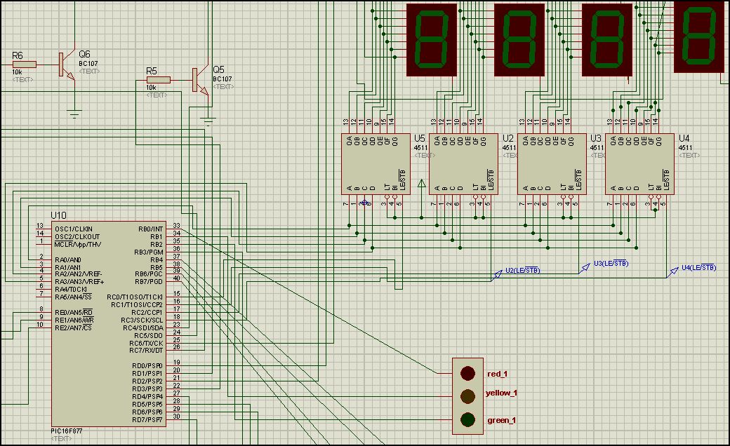
o you know how we can make bus wire in Proteus?

thanks in advance.
 

Its the sixth icon under the arrow (in the left icons), a thick line with small lines up and down.
You create a thick bus and than you have to add individual nets going in and then out of the bus, you have to use label in each wire going to or leaving from the bus.

For example you can connect a wire to the bus and put a label to that wire PA1 then in the other side of the bus you will also put a wire for output and place the same label (PA1) so that proteus knows where this wire connects, you can also have multiple outputs from the same input.

Alex

---------- Post added at 11:17 ---------- Previous post was at 11:11 ----------

Experiment buses in a blank project and use logicstate as input and logicprobe as output

Alex
 
Status
Not open for further replies.

Similar threads

Part and Inventory Search

Welcome to EDABoard.com

Sponsor

Back
Top