Continue to Site

Welcome to EDAboard.com

Welcome to our site! EDAboard.com is an international Electronics Discussion Forum focused on EDA software, circuits, schematics, books, theory, papers, asic, pld, 8051, DSP, Network, RF, Analog Design, PCB, Service Manuals... and a whole lot more! To participate you need to register. Registration is free. Click here to register now.

[SOLVED] 6v, 4.2mAh Battery charging problem

Status
Not open for further replies.

speedEC

Full Member level 6
Joined
Apr 1, 2011
Messages
337
Helped
23
Reputation
46
Reaction score
21
Trophy points
1,298
Activity points
4,324
Dear all,

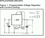
I have made a battery charging circuit using "L200" for my 6v, 4.2 mAh sealed alkaline battery (usually seen at emergency lamp). The circuit is based on the datasheet of L200.
SP32-20110529-115935.gif

I have used 9v, 500mA AC to DC Adopter for charging the battery. When I measure the voltage output on the circuit (Not Connected to Battery), the multimeter shows 9v. The voltage output on PIN5 is 5.49v. 10K Resistor (R3) placed between PIN5 and PIN2. So the output current (max) is: I = ((V5 - 2) / R3). i.e. (5.49v - 2) / 10K = 0.349 amps or 349mA. Right? But, I don't know how to measure the amps flowing into the battery. I can't able to know whether my battery is charging correctly or not. Can anyone help me i this regard.

Thanks
pmk
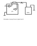
 

If your circuit is like in schematic, there is a series resistor R3.

Battery charging current flow through this resistor.

If you measure voltage over that resistor, you can calculate the
current in that resistor.

I = U / R

I= current in R3
U= measured voltage over R3
R= value R3

Regards KAK
 

Thanks for your response KAK. I measured the voltage on R3. Between PIN5 and R3(10K resis) is around 5.46v. Between R3 and PIN2 is around 7.55v. Which voltage should be used to calculate the current? Pl help.
thanks
pmk
 

Resistor R3 is between pins 5 and 2. Current set resistor,
this is small ohms. (Not 10kohm )

Meter plus to pin 5 and meter minus to pin 2.

That is voltage you need. Then I= measured U / R3 value.

Load must be connected, before you can find out the current.

What is R3 value in your circuit.

KAK


R3 is series resistor in current output pin 2.

Your circuit output current max. is U5-2 / R3

Look yours attached picture

ie. output current 0.5A and 6V

calculate R3 = 6-2 / 0.5 ::: R3 = 2 ohm

Load must be connected, before you can find out the current in load.

KAK
 

Meter plus to pin 5 and meter minus to pin 2.

I measured the voltage between PIN5 and PIN2 as you suggested. The voltage around -0.99v. But, If I measured the voltage

1. between PIN5 and GND is +5.46v.

2. between PIN2 and GND is +7.40v

(PL NOTE: Battery Connected to the Circuit)

What is R3 value in your circuit.

I have used 10K as R3 (Between PIN5 and PIN2).

pmk

---------- Post added at 15:43 ---------- Previous post was at 15:35 ----------

calculate R3 = 6-2 / 0.5 ::: R3 = 2 ohm?

8ohms? Am I right. So, I can use around 8 ohms.

R3 = (V5 - 2 / I) = (5.46 - 2) / 0.450 = 7.6 ohms = 8 ohms

thanks.
 

while you know that I=V/R, if you make R=1 ohm, then I becomes equal to voltage aross the 1 ohm.
thus you place a 1 ohm in series with the connecting to charger.
select a 10 watt 1 ohm resistor. place your digital DC voltmeter across it, the reading is +current flowing thro it.
for higher currents have a 0.1 ohm resistor and the voltage is 10 times the voltage measured across 0.1 ohm.

hope this serves
 

Thanks mvs sarma. I don't have 8 ohms resistor on my hand now. I have only 10 ohms(1/4 watt) resistor. So, I can get the output current of 0.346 Amps. Am I right?

R3 = 10 ohms
V5 = 5.46v

I (max) = (V5 - 2) / R3 = (5.46 - 2) / 10 = 3.46/10 = 0.346 Amps.
 

same head , same brains alldays
of course 8 ohms.

Check power dissipation on series resistor.

P = I^2 * R
0.35 * 0.35 * 10 = 1.23 [W]
 
Last edited:

it is not like that
measure the voltage across the pins 5 and 2 divide by the Value of resistor you use

In general, the V(5-2)means voltage difference between pins 5 and 2 and not voltage at pin5 -2

you can safely assume for a 2 watt or so resistor usedbetween pins 5 and 2, the voltage would be around 0.45V
thus Iout can be 0.45/R3
 

thanks to all for the timely help you provided. I have used 10 ohm resistor (R3). But, still I have trouble to read the current supply (to Battery). If possible pl help me to measure Amps.

One more help: Where can find I "Helped Me" button? Shall I give the points who helped me?

---------- Post added at 16:29 ---------- Previous post was at 16:24 ----------

it is not like that
measure the voltage across the pins 5 and 2 divide by the Value of resistor you use

In general, the V(5-2)means voltage difference between pins 5 and 2 and not voltage at pin5 -2

you can safely assume for a 2 watt or so resistor usedbetween pins 5 and 2, the voltage would be around 0.45V
thus Iout can be 0.45/R3

The voltage between PIN5 (multimeter +) and PIN2(multimeter -) is around -0.99v.
The voltage between PIN5 (multimeter -) and PIN2(multimeter +) is around +0.99v.

Is this reading correct or wrong?
 

I think something is wrong.
If U5 is lower than U2 battery is discharged.
Voltage U5 should be more positive.

Look picture.............

Batt_load_01.jpg


Sealed Lead-Acid Battery Charger Circuit

Read last part
Diode protection for the L200 regulator?

KAK
 
Last edited:

The circuit I drawn looks same. Also, I have used IN4007 Diode to protect the current flow from battery into circuit. I have little doubt here. 10K pot should be connected between PIN2 and PIN4 as shown in the diagram. We have 3 pins on POT. One is connected to +ve and another one to GND and remaining one (center pin) to PIN4. I have extended this junction to PIN2. Is this correct? if it is wrong pl correct me.
Thanks.
 

one datasheet indicates , in general the voltage across p5 and p2 is 0.45V. for 4 amps you can calculate

for current measurement into the battery, you may have a 1 ohm in series to the battery path from pin2. voltage across it , would be current thro the path to battery.
 

Attachments

  • l200circuitdiagram.pdf
    46.9 KB · Views: 137
Last edited:
one datasheet indicates , in general the voltage across p5 and p2 is 0.45V. for 4 amps you can calculate

for current measurement into the battery, you may have a 1 ohm in series to the battery path from pin2. voltage across it , would be current thro the path to battery.

I have little doubt here. 10K pot should be connected between PIN2 and PIN4 as shown in the diagram. We have 3 pins on POT. One is connected to +ve and another one to GND and remaining one (center pin) to PIN4. I have extended this junction to PIN2. Is this correct? if it is wrong pl correct me.
 

Pot.meter connection

if you turn potentiometer full CW ie. maximum setting,
middle and other resistor end pin resistance is about 0 ohm ,
connect those together and that to L200 pin 2.
Pot.meter free end pin to L200 pin 4

Now should L200 output go higher, when you turn pot. CW.

KAK

PS. Between pot. meter end pins is fixed resistor, same as pot.meter value.
middle pin is slider between end points.
 

Both side end pin (1 and 3) should be connected together to PIN2 and Slider pin (2 - center) should be connected to PIN4. Am I correct?

I have measured the volt across PIN5 and PIN2. now it is 0. I don't know whats going on there in the circuit.

One more thing: My 6v 4.2mAh battery now indicates it is 6.75v. Previously (Yesterday) it shows 5.5v. I believe that the circuit works now. But, I need concrete circuit but not in luck.
thanks
pl help.

thanks.

---------- Post added at 19:36 ---------- Previous post was at 19:28 ----------

Potentiometer has been connected as you suggested. It works now better than earlier. But, still voltage across PIN5 and PIN2 is 0.

thanks
pmk
 

still voltage across PIN5 and PIN2 is 0.

This voltage is zero until ( load) charging current goes through R3 (10ohms)

When L200 regulator output voltage (pin 5 ) goes higher than
battery charge voltage + your series diode ( 0.7...0.8V )
Current flows to battery and voltage pin5 to pin2 appears
as U = I/R.

if battery is lead acid type voltage pin5 should be about 6.8V ( + series diode ( 0.8V))
for normal charging.

KAK

PS. More info in electronics you find in my group, join , you are welcome

One more help: Where can find I "Helped Me" button? Shall I give the points who helped me?

It´s down here: Thumb up
 
Last edited by a moderator:
Status
Not open for further replies.

Similar threads

Part and Inventory Search

Welcome to EDABoard.com

Sponsor

Back
Top