stark43
Member level 1
Hello,
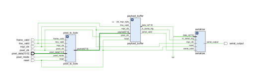
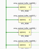
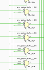
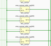
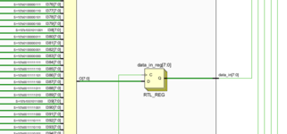
I want to serialize 640 byte pixel data and I used line buffer for this and when I looked at the schematic I got scared and I think I made a mistake. Are there any nicer ways to save 640 bytes into memory? Sorry for my inexperience.
I want to serialize 640 byte pixel data and I used line buffer for this and when I looked at the schematic I got scared and I think I made a mistake. Are there any nicer ways to save 640 bytes into memory? Sorry for my inexperience.