Continue to Site

Welcome to EDAboard.com

Welcome to our site! EDAboard.com is an international Electronics Discussion Forum focused on EDA software, circuits, schematics, books, theory, papers, asic, pld, 8051, DSP, Network, RF, Analog Design, PCB, Service Manuals... and a whole lot more! To participate you need to register. Registration is free. Click here to register now.

60601-1 Creepage Requirements

Status
Not open for further replies.

eephoto

Newbie level 2
Joined
Nov 12, 2010
Messages
2
Helped
0
Reputation
0
Reaction score
0
Trophy points
1,281
Activity points
1,295
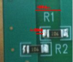
Our creepage requirements from SFTY_GND to Protective_Earth Ground are 2.3mm. So to meet the creepage requirements we have a 3mm gap between SFTY_GND and Protective_Earth Ground shown in the attachment as Dim A but I have a question about this. I have two resistors in series each 10Mohms each in parallel with a Capacitor for filtering, so Dim B which is less then 2.3mm is that going to be ok since we have a high impedance path?
 

Attachments

  • Actual_PCB.JPG
    Actual_PCB.JPG
    16.8 KB · Views: 65
  • Schematic.JPG
    Schematic.JPG
    26.2 KB · Views: 65

It is a while since I have looked at 60601 but while I think your clearance is ok, I don't think you can include the capacitor. I will try to check later today when I am at my computer.

Keith

---------- Post added at 07:00 ---------- Previous post was at 06:57 ----------

Actually, I think there may be a problem with the clearance. While you can ignore the resistor, you have the pad between the two grounds which shortens the creepage path. You need to fix that I think.

Keith
 

Do you think the capacitor is a problem because of the crevice that is formed between the capacitor and PCB, which may cause polluntants to easily build up?
While you can ignore the resistor, you have the pad between the two grounds which shortens the creepage path. You need to fix that I think.
Isn't the Pad basically a floating piece of conducting material which I think according the the 60601 specfications is ok.
 

I cannot remember the reason for having to remove the capacitor - it may just be that you aren't allowed any earth leakage, or at least a very tiny amount compared to normal equipment. Look at mains inlet filters and you will see the medical grade ones have no class Y capacitor to earth.

The resistor has a floating pad which reduces the clearance (assuming your dimension A was 3mm). Your creepage distance is from the edge of the ground plane to the first edge of the resistor pad plus the distance from the other side of the pad to the other ground plane or 3mm less the pad width. That would be my assessment anyway - I am not a standards expert but I am forced to read them from time to time.

Keith

PS a quick search suggests maximum 100uA earth leakage and 500uA under single fault conditions. I think that is why you cannot have the class Y capacitor there (or maybe a very small one).
 

Status
Not open for further replies.

Part and Inventory Search

Welcome to EDABoard.com

Sponsor

Back
Top