Continue to Site

Welcome to EDAboard.com

Welcome to our site! EDAboard.com is an international Electronics Discussion Forum focused on EDA software, circuits, schematics, books, theory, papers, asic, pld, 8051, DSP, Network, RF, Analog Design, PCB, Service Manuals... and a whole lot more! To participate you need to register. Registration is free. Click here to register now.

5v power supply filtering.

Status
Not open for further replies.

deepu.deep2112

Newbie level 6
Joined
Sep 23, 2013
Messages
13
Helped
0
Reputation
0
Reaction score
0
Trophy points
1
Location
Chennai
Activity points
94
Hi,
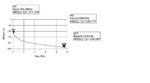
For designing 6 bit digital attenuator in receive chain of receiver, I have provided 5v supply to vee terminal from normal smps.so for filtering 5v I have added 4.7uf, 0.01uf and 0.1uf in parallel manner.I am planning to simulate the same.kindly tell me, the average rangefrequency of the 5v signal.my application is in x band.so my filter should provide rejection up to how much freq and what should be rhe avg rejection.
 

Your blocking capacitors look good. What are the frequencies of interest in your receiver?
To calculate filtering properties you must know the source impedance of your 5V supply and load impedance presented by your attenuator.
 

Its x band 9.3 to 9.5 GHz and load as well as source impedance is 50 ohms.I have selected coupling and decoupling capacitor of 0.1uf.
 

I am nt interested to block dc, I am interesting in filtering out the frequencies which may get coupled through power supply path and will create spurious to other device which is connected through same supply if the filter doesnt provide sufficient rejection.
 

How I view power supplies/ripple/noise/filters is that the pcb layout and component locations must take priority in the design.
Put simply keep the loops for the DC output to ground via the decoupling capictor as short as possible. For the higher frequency components keep their loop the shortest, so the ceramic as close as possible to the DC out.

In fact keep the capacitors in order of their value i.e. decreasing the distance with the decreasing values.

I would also use some good ceramic capacitors and surface mount give the best performance.

Next if you really want to get the PSU noise down add a series inductor (examine ferrite beads) on the DC output (after the above capacitors) and decouple the output from the inductor with some further ceramics.

BUT except for some type of modulation effects that may be an issue, your DC supply noise should be significantly away from your frequencies of interest.

Look up things like series resonance for capacitors and you will see that most don't go past MHz for effective decoupling.

I stand to be corrected, but I would be ssuprised of any PSU noise with your decoupling and a good layout affecting GHz.
 

Thanks for guidance.by d way I forgot to mention that I have used 0.0038nH inductor in seriea path between 4.7uf and 0.1uf parallel caps.
 

For very high frequency circuits I would expect some decoupling capacitors a lot lower than 100nF. You need the SRF of at least one capacitor to be above the frequency you are working at. You can end up with several capacitors with the smallest around 47pF.

Keith
 

Actually I have simulated the filter chain as i have mentioned above with 4.7,0.1 & 0.01uf capacitors in parallel manner and one inductor 0.0038uH in series upto frequency 10GHz.I founs a good rejection at higher frequencies.I think that is sufficient for me.Attached is ADS simulation result.
 

Attachments

  • Filter simulation.jpg
    Filter simulation.jpg
    52.8 KB · Views: 62

Does your simulation include all parasitic effects of the inductor and capacitors? I presume not.

Keith
 

Actually for simulation I have not used lumped network but I have used S2P files which I had got from vendors and simulated the same in ADS.
 

What specific capacitors and inductors are you using? Your results don't look "real" to me.

Keith
 

Component details

4.7uf - GRM21BR71C475KA73L
0.1uf- ATC545L104KT16T
0.01uf - ATC520L103KT16T

- - - Updated - - -

inductor is -- 0302CS-3N8XJLW
 

Status
Not open for further replies.

Part and Inventory Search

Welcome to EDABoard.com

Sponsor

Back
Top