Continue to Site

Welcome to EDAboard.com

Welcome to our site! EDAboard.com is an international Electronics Discussion Forum focused on EDA software, circuits, schematics, books, theory, papers, asic, pld, 8051, DSP, Network, RF, Analog Design, PCB, Service Manuals... and a whole lot more! To participate you need to register. Registration is free. Click here to register now.

555 timer output amplification problem

Status
Not open for further replies.
Why didn't you look at the datasheet of the 2N3904 to see that its maximum allowed current is only 200mA and its performance above 100mA is poor?
The maximum output current of a 2N2222, 2N4401 and hundreds of other transistors is 600mA or more and will work much better. The base resistor should be 180 ohms.
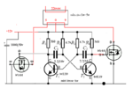
Knowing Indian market I suggested the use of darling-ton transistor. but if you try with SL100/Cl100/n100 it can be achieved
 
Why didn't you look at the datasheet of the 2N3904 to see that its maximum allowed current is only 200mA and its performance above 100mA is poor?
The maximum output current of a 2N2222, 2N4401 and hundreds of other transistors is 600mA or more and will work much better. The base resistor should be 180 ohms.

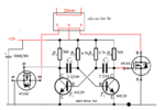
hmm depending on datasheets i stopped making practice with all of them & moving for mosfets cause 2N2222 is having same issue so now i ve to check rest others depending on respective datasheets
 

so suggest me some other one please
There are thousands of modern transistors and ICs here in The West. Maybe there are only a few old ones (maybe not made anymore) in your country.

I have never seen a 2N2222 transistor or an SL100 transistor that are common in your country.
I think I saw a 741 opamp about 40 years ago.
 
There are thousands of modern transistors and ICs here in The West. Maybe there are only a few old ones (maybe not made anymore) in your country.

I have never seen a 2N2222 transistor or an SL100 transistor that are common in your country.
I think I saw a 741 opamp about 40 years ago.


There are thousands of modern transistors and ICs here in The West. Maybe there are only a few old ones (maybe not made anymore) in your country.

I have never seen a 2N2222 transistor or an SL100 transistor that are common in your country.
I think I saw a 741 opamp about 40 years ago.


sir its not a matter relating availablilty in country or anywhere else , my mission is to introduce tech with very very very common things available "TO EACH & EVERY PART OF THE COUNTRY INCLUDING RURAL & URBAN AREAS". . let me clear , that i succeed so many things since last 2 years with all your help & bless & with
"that available things only"
A few things left for some projects that need some online buying or other sources
yaa i agree cause i hv no option but incase for very cheap & too rare available devices i need substitutes cum modification & i know you can make it possible . . & country is not matter here cause proof is around me in my lab where small functions are going on hand's click or finger chucks & mouth whisperings (no matter power is present or not) :)
I always need all your deep experience & knowledge for the purpose if have get problem regarding designs or substitute blah blah blah
but i don't want to make expenditures for every single & cheap device as i ve to introduce tech.home to home,every grade, poor or rich . . .
All time people don't show intrest for such introductions as they know technology means money matter or just due to this unavaiablity of components in their area . .
Too if i buy things from internet or any other far sources & any compllication happens in the project or plan then the person has to be depend on me or anyone who have any idea about it , then finally he ll blame me at the moment
i wanna make them independent for such small & small daily use imp units i am providing them for safety,communications,etc etc etc & too
these things help them increasing technical skill which may help them in many aspects of life . . so many things are corelated here sir . .
i can't explain everything
No matter it is available in any part of my country or not , but something are avaiable in each & every part here . ,
now let me clear some of that common things :
bc547 548 557 558 SL100 2N2222 2N3055 IRF44 630 etc
555 741 386 4017 4047 358 4558 4093 etc etc etc etc
& so many things are avaiable in COMMON but if incase anything is rare say demand once in 3 years then who ll take intrest in selling such IC or transistors ? They have to purchace a single piece for me from a whole seller & what it costs after a long argument with whole seller,you can imagine that :p , who ll take such stress for my
"experiments for sake of humanity"
a very short example is here :-
These days we are not getting radio parts like coil ferrite rod gang controls etc etc etc which were avaiable at a 100m distance & some 15 years ago & we applied these radio parts for some diffrent projects avaiable in local market but if some one demands us the same thing with same cost , we cant do it though we can with same rates but due to unavailablity of components in nearby region its not possible to do it in same rate figure
so many of my projects are hanged or on hold due to such reasons
& unlike me everyone is not interested to do such experiments with technology so i am suffering problem of easily available sources . .
May be tommorow much of them are avaiable (just like every datasheets on google) then it would get much easy but for that time i can't wait as in today's world condition is going worst & worst . .
crime rates , women assault , cyber crime etc etc etc
.
.
well i did experiments with 2N3055 & SL100 but still failed & now its time to move for a mosfet
.
.
here i got a diagram while googling about IRF44

**broken link removed**

is that ok ?
 

You did not show your schematic of the circuits that did not work with 2n3055 and SL100 transistors so we cannot help you fix them.

Nobody makes an IRF44 Mosfet so no datasheet is made for it.
Your attachment 103553 does not work.
 

You did not show your schematic of the circuits that did not work with 2n3055 and SL100 transistors so we cannot help you fix them.

Nobody makes an IRF44 Mosfet so no datasheet is made for it.
Your attachment 103553 does not work.


its just very simple , collector direct to vcc 12 volts 1.5 amps
from vcc to base a resistor is there with value 180 ohms & load i.e. the LED strip is connected in between emmiter & ground , all the assembly is mounted on a bread board & power supply is the one i designed by your help !

- - - Updated - - -

here is the attachment again which was not working

diag1rf44mod.1.png
 

The 400mA LED strip should be driven pretty well by a 2N3055 or SL100 transistor with a 180 ohm base resistor from a 555 with a 13V supply.
At only 400mA the voltage loss in the transistor is fairly low.
Your result was poor because your transistor was an emitter-follower with a high voltage loss, not as a switch. Your LED strip got only about 8.7V.


Your Mosfets are IRFZ44, not IRF44.
A Mosfet has a high gate-source capacitance that slowly ramps its turn on time when its is turned on by a resistor as high as 560 ohms. Then it heats up during the ramping. The heating will be less when the gate is driven from an NPN-PNP pair of emitter-followers as shown earlier in this thread.

- - - Updated - - -

You should not use a breadboard for (anything!) high current circuits.
 
Last edited:
okk i see , kindly tell me that what configuration should i apply in place of emitter follower so as to run fairly with SL100 etc ??

I too connected IRFZ44 but getting same result as like before (lil.bit lower brightness)

and why should we not use breadboard for high currents ?
then where to perform practicals ? is there any other option or board for such high current operations ?

please please comment all
 

With a 12V supply, the typical output high voltage from a 555 driving a 2N4401 emitter-follower transistor with 40mA is +10.5V. The typical output of the emitter-follower with a 400mA load is only +9.5V. But the voltage losses can be much higher.

If the 555 drives the 2N4401 transistor as a switch (common-emitter, look in Google) with a base current of 40mA and a load current of 400mA then the load typically gets 11.75V.

If the 555 drives an IRFZ44 Mosfet as a common-source switch then the 400mA load gets 11.99V. The LEDs WILL NOT be dimmed unless the contacts on your breadboard have a high resistance.

It is all shown on the datasheets.

The contacts on a breadboard are designed for low current and frequently are corroded or weakened.
I use parts soldered on stripboard for most of my prototypes.


kk fine ! for present i removed the 55 part & only make it with mosfet transistors etc due to the problem i am facing . .
so as per your explanation i ve to make it soldered first . .
well , sir what about the diagram i uploaded ? ? ?

diag1rf44mod.1.png
 

what about the diagram i uploaded ? ? ?

View attachment 103590
Didn't you see my reply about it in post #30?
I said: A Mosfet has a high gate-source capacitance that slowly ramps its turn on time when its is turned on by a resistor as high as 560 ohms. Then it heats up during the ramping. The heating will be less when the gate is driven from an NPN-PNP pair of emitter-followers as shown earlier in this thread.
 
  • Like
Reactions: rajaram04

    V

    Points: 2
    Helpful Answer Positive Rating

    rajaram04

    Points: 2
    Helpful Answer Positive Rating
Didn't you see my reply about it in post #30?
I said: A Mosfet has a high gate-source capacitance that slowly ramps its turn on time when its is turned on by a resistor as high as 560 ohms. Then it heats up during the ramping. The heating will be less when the gate is driven from an NPN-PNP pair of emitter-followers as shown earlier in this thread.


kk it was for the ckt . . i thought its one of the property you are explaining about
 

Didn't you see my reply about it in post #30?
I said: A Mosfet has a high gate-source capacitance that slowly ramps its turn on time when its is turned on by a resistor as high as 560 ohms. Then it heats up during the ramping. The heating will be less when the gate is driven from an NPN-PNP pair of emitter-followers as shown earlier in this thread.


well sir SL100 & 2N3055 are doing much better work as the have high Ic as per datasheets . . but i ve problem with mosfet biasing as i am unable to do so properly , my very first step is lagging . .
i connected drain to Vcc , a load between source & ground , a 100k resistor from gate to earth , now when i connect gate to plus line via 180 ohms as per your suggestion , a very very small output i am getting at the load . . .
whats going on actually ?
please help me in proper mosfet biasing for IRFZ44
so many circuit diagram are present on net world with a very simple configuration for this one but i failed with all of them . .
 

With that mosfet, the load should be connected to Vcc, drain to load, source to ground. That is a "low" configuration. Otherwise, you need to boost the gate voltage to Vcc + 10V (+/-).

In the "high" configuration you describe, when the mosfet turns on, the voltage drop across it is very low. Therefore Vsource ≈ Vdrain ≈ Vcc. Thus, the gate must be >>Vcc if Vgs is to be 10V.

As you point out, there are a lot of circuits on the Internet, and it can be confusing. It is even more confusing when we don't know the circuit you are actually using. Please post the mosfet circuit you are actually using at this point.

John


i see . . thanks for such a nice explanation

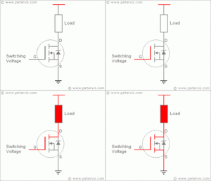
well here is the diagram what i actually need to design very first

dsf.gif

a lil.bit change in the diagram is the absence of external switching voltage , i just want to trigger gate with Vcc itself . .

i need this very firstly then only i can design any other triggering ckts or anything

supply parameters for present operation is 12v 1.5A
 

You said you used the Mosfet as a source-follower with the drain at Vcc and the load from the source to ground. Then it is not a switch and needs a very high gate voltage. Then you posted a correct schematic that you did not use.
 

Attachments

  • Mosfet.png
    Mosfet.png
    11.5 KB · Views: 73
You said you used the Mosfet as a source-follower with the drain at Vcc and the load from the source to ground. Then it is not a switch and needs a very high gate voltage. Then you posted a correct schematic that you did not use.


ya posted an example of what i am doing , the change is the position of load but now i got it & everything is cleared now
 

Status
Not open for further replies.

Part and Inventory Search

Welcome to EDABoard.com

Sponsor

Back
Top