Continue to Site

Welcome to EDAboard.com

Welcome to our site! EDAboard.com is an international Electronics Discussion Forum focused on EDA software, circuits, schematics, books, theory, papers, asic, pld, 8051, DSP, Network, RF, Analog Design, PCB, Service Manuals... and a whole lot more! To participate you need to register. Registration is free. Click here to register now.

555 monostable + off indicator

Status
Not open for further replies.

this

Member level 2
Joined
Apr 14, 2011
Messages
44
Helped
4
Reputation
8
Reaction score
4
Trophy points
1,288
Activity points
1,623
Welcome people of earth.

I have a basic monostable 555 circuit with a LED on the output.
I want second LED that would be on when the "main" LED is off and vice versa.
My idea was:
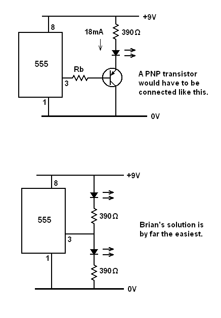
connect PNP transistor: base to 555 output(pin 3), colector to 9V, and LED+resistor between emitter and ground.
I thought that when monostabe is off, then 555 pin 3 is low, and transistor should let the current flow into second LED, and when monostable goes on, then current from pin 3 should close the transistor and second led should go off.

It is not working, can somebody please explain why?
bgrds.
 

it might be the case that if you connect first the resistor than the led, i.e. emitter of the transistor-> resistor -> led -> ground, it might not work. the pnp transistor can drive a certain amount of current and this current causes voltage drop on the resistor. so if the voltage left for the led is not enough for the led, the led might not work. to fix this you might try to use a resistor with a smaller value.
also you may try to use a cmos inverter to drive the second led, it won't use any current, so it won't effect the main led.
post me back if you can fix the problem, I also wonder what the problem is.
 

You say you're putting a load at the emitter leg of a PNP.
(Transistor nomenclature is funny, isn't it?)

That would imply it's above the transistor?

An led requires at least 1.8V before it passes current.

This changes the bias requirements. The transistor may not turn on at all.

Or did you put the led in the collector leg (lower)?.

Notice that the bias needs a resistor to limit current through it... If you're not careful you'll fry the transistor and the 555.
 

The 555 can sink and source current. Why not connect its output directly to two LED/resistor chains, one connected to +Ve supply and one connected to ground?

Brian.
 

Brian: your solution sounds so obvious I can't believe I didn't figured it out myself, thx :)

Rest of you good people:
Thats right, led is on the collector and emitter is grounded.
So the whole idea with PNP is theoretically ok?
How do I calculate resistances?
"main led" - what resistance? I have 470 ohm now - it's ok when the led is the only output, do I have to change it when Pin3 is also connected to
base of my PNP? and do I need an additional resistance before base? how to calculate it?

thanks
 

Collector toward positive, emitter toward negative, is conventional use of NPN. The emitter emits electrons. The collector collects them. But only with NPN.

Back when they started making PNP transistors, the nomenclature got topsy-turvy. I think they did it to keep the idea that the emitter carries combined bias and load currents (in most applications). This allowed spec tables to be simplified.

Hence with PNP, the collector is toward negative and the emitter toward positive. The collector emits electrons and the emitter collects them.

---------- Post added at 15:15 ---------- Previous post was at 14:17 ----------

How do I calculate resistances?
"main led" - what resistance? I have 470 ohm now - it's ok when the led is the only output, do I have to change it when Pin3 is also connected to
base of my PNP? and do I need an additional resistance before base? how to calculate it?

First I gotta say, Brian came up with the best solution. It will do the job. 470 ohms is suitable in series with each led. Above 9V supply voltage you will need to increase the ohms.

As for operating a transistor...

The base of a transistor carries minute current. Normally a few mA at most.

You can start with a 100K resistor (or potentiometer). Attach it to the base.

Reduce your resistance gradually to increase current through the base. Stop when your load is getting the desired current.

IMPORTANT: You must not allow base current to exceed spec. (Usually a few mA.)

Say you want 10mA through your load...

and your transistor has 100 gain...

then you need .1 mA through the base.

Your supply might be 5V...

then you use 50k resistance at the base. This is just a simple calculation for a bare led.

You may want to keep the 470 ohm resistor inline with the led as protection. Then you can reduce bias resistor to 2200 ohms.

I'm using a simulator to arrive at the values which work.
 
Last edited:

So the whole idea with PNP is theoretically ok?

The trouble with that is the very low voltage which would be available across the transistor's base resistor, making calculation of its value a bit awkward - not knowing the actual Vo of the 555.

Twoledsat555output.gif
 

Status
Not open for further replies.

Part and Inventory Search

Welcome to EDABoard.com

Sponsor

Back
Top