Continue to Site

Welcome to EDAboard.com

Welcome to our site! EDAboard.com is an international Electronics Discussion Forum focused on EDA software, circuits, schematics, books, theory, papers, asic, pld, 8051, DSP, Network, RF, Analog Design, PCB, Service Manuals... and a whole lot more! To participate you need to register. Registration is free. Click here to register now.

555 monoshot-- loading effect

Status
Not open for further replies.

vinodquilon

Full Member level 3
Joined
Oct 24, 2009
Messages
158
Helped
2
Reputation
4
Reaction score
2
Trophy points
1,298
Activity points
2,558
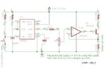
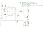
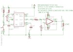
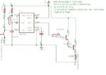
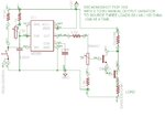
I want to give 5V-1ms pulse to a resistive load using 555 monoshot.
First I am connecting 33 Ohm, then 68 Ohm and finally 100 Ohm as load.

Can I use the same 555 circuit for all the above three cases without any loading and voltage dipping problems ?


How can I vary the amplitude of 1ms pulse output from 0V to 5V in steps of 0.5V without adjusting 555 supply voltage?
 

final schematic

Here is my final schematics....(one using OP AMP and other using BJT).
Kindly give me necessary advice on selection between the two ones that is better?

Is there any mistakes in my design and selection of components ?
After getting a clear answer I will go for hardware implementation.
 

Attachments

  • 555(BJT).jpg
    555(BJT).jpg
    55.1 KB · Views: 89
  • 555(OPAMP).jpg
    555(OPAMP).jpg
    61.4 KB · Views: 97

I think the 555 is good with > 1 kOhm load. Your low ohms will overload the 555 output. Using a LM741 is possible, I think one transistor can make it much easier. Controlling pulse amplitude can be made by a "volume control" potentiometer e.g. across the output (5-10 kOhms), assuming the output is AC coupled.
 
assuming the output is AC coupled.

I am looking for one shot pulse output not ac sine wave.

- - - Updated - - -

Using a LM741 is possible, I think one transistor can make it much easier. Controlling pulse amplitude can be made by a "volume control" potentiometer e.g. across the output (5-10 kOhms)

As per one of my friends suggestion-----

The pot in parallel with the load in the first circuit will not give the required variation in pulse amplitude.
The 741 opamp has an output current of ~25mA max; not enough to drive those loads.
Neither circuit has a way of stepping the output level.
 

I am looking for one shot pulse output not ac sine wave.

- - - Updated - - -


As per one of my friends suggestion-----

The pot in parallel with the load in the first circuit will not give the required variation in pulse amplitude.
The 741 opamp has an output current of ~25mA max; not enough to drive those loads.
Neither circuit has a way of stepping the output level.

AC coupled pulse output is not a "sine wave". If you want to use simple "power" circuits like shown in your schematics, you will need AC coupling. The transistor in your schematic as well as the 741 will die soon if loaded with your hard load. You should find a two-or four-transistor power buffer bridge to handle your load.
One more idea: If your pulse shape (duration not defined) is not too important, you can try to use an audio transformer with a primary impedance of > 500 Ohms and secondary ~100 Ohms can be used directly with a 555.
 

Darlington output stage

Does this works !!!!!
 

Attachments

  • 555(BJT_1).jpg
    555(BJT_1).jpg
    55.7 KB · Views: 63

By connecting the transistors as shown it may work only once. 10 V and low load will burn both transistors.
Use protective resistors around.
 

modified design

Pls find the modified schematic.....Is it OK ?

Can I produce the low values like 0, 0.5, 1.0 V by turning 5K ? (also 1.5, 2.0, 2.5, 3 medium values & 3.5, 4, 4.5, 5V high values at output of darlington)
 

Attachments

  • 555(BJT_3).jpg
    555(BJT_3).jpg
    61.4 KB · Views: 77

555-opamp-bjt

555-OPAMP-BJT
Here is 555 oneshot with LM324 & 2N2222 for 0-5V continuous amplitude variation of 1ms pulse.:)

Any rectifications ?
 

Attachments

  • 555(OPAMP-BJT).jpg
    555(OPAMP-BJT).jpg
    60.2 KB · Views: 77

Problem continues....

The following are the difficulties I have faced during the above circuit implementation,

1. 1ms pulse by pressing the trigger micro switch is hard to achieve as it depends on the duration of pressing the switch and is beyond 1ms (depends on the operating person)

2. To overcome the above difficulty I have designed one 3ms 555 astable and is fed to monoshot through Differentiator

3. In the 2nd case I cannot control the count of mono pulses at output as I only want a SINGLE 1ms pulse at 555 mono out.

:confused:
 

optimized schematic

optimized schematic to overcome above mentioned difficulties..:grin:
 

Attachments

  • 555 v3.1.png
    555 v3.1.png
    18.2 KB · Views: 79
Last edited:

Status
Not open for further replies.

Part and Inventory Search

Welcome to EDABoard.com

Sponsor

Back
Top