Continue to Site

Welcome to EDAboard.com

Welcome to our site! EDAboard.com is an international Electronics Discussion Forum focused on EDA software, circuits, schematics, books, theory, papers, asic, pld, 8051, DSP, Network, RF, Analog Design, PCB, Service Manuals... and a whole lot more! To participate you need to register. Registration is free. Click here to register now.

500W Full Bridge is giving too high delta B even with biggest core available

Status
Not open for further replies.
Z

zenerbjt

Guest
Hi,
Just done the Transformer design for 500W Full Bridge with current doubler output.

Vin=400V
Vout = 24V
Pout = 500W
"Overall switching" frequency = 80kHz though primary magnetising current is like at 40kHz (as attached)
(Each diagonal FET pair switches at 40kHz, but together the two diagonal pairs of the bridge switch at 80kHz)

Even if I use the biggest offtheshelf core available (ETD59 by TDK), then I have a primary delta B which is going from +0.238T to -0.238T. This is too much. I am seeing 10W of loss in the core using N87 material, which is too much.

Do you know of any other bigger cores?

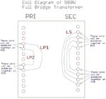
Attached is the PDF schem, the LTspice sim and the waveform shot showing primary current and primary magnetising current.

ETD 59 core datasheet

(EDIT................., ive just now increased the primary turns from 20 to 40, giving LP=8.48mH (and kept same NP/NS) and now am at +0.119T to -0.119T...still too much.....i dont want too much primary inductance otherwise the leakage inductance will be too big and i will "loose duty cycle" due to rise time of primary current being slowed. Actually, with LP=8.48mH i am getting 2.5W core loss with N87 material.)
 

Attachments

  • Full Bridge _Current Doubler.pdf
    110.1 KB · Views: 144
  • Full Bridge 500W.jpg
    Full Bridge 500W.jpg
    79.7 KB · Views: 167
  • Full Bridge _Current Doubler.zip
    1.6 KB · Views: 116
Last edited by a moderator:

PM87 is a good sized core

simple pri over sec ( or similar ) will give a lot of extra wire losses at 80kHz, or even 40kHz, internal layout of the various wdgs is very important above 20kHz ...
--- Updated ---

In your picture the Imag looks to be very high ( compared to the load current ) usually 10%, maybe your output chokes need to be a bit bigger - say 20% Iripple max in these ... design of current double chokes can be tricky - it is a trade-off of peak current ( peak B ) vs rms current and conductor losses due to the current ( and hence flux ) ripple ...
--- Updated ---

p.p.s if any pair of fets switches at 40kHz - then the Tx is driven at 40kHz ( not 80kHz ) the output ripple after rectifying can be 80kHz ...
 
  • Like
Reactions: zenerbjt

    Z

    Points: 2
    Helpful Answer Positive Rating

    Velkarn

    Points: 2
    Helpful Answer Positive Rating
Your transformer fundamental frequency is 40 kHz. According to MDT, +/- 0.22 B is feasible with 25K core temperature rise, giving > 4 kW transferred power for ETD59. Even at +/- 0.15 B (+10 K), 3 kW can be transferred.

There are however bigger cores if actually required, presume you have TDK and Ferrocubes catalogues at hand.
 
Your transformer fundamental frequency is 40 kHz. According to MDT, +/- 0.22 B is feasible with 25K core temperature rise, giving > 4 kW transferred power for ETD59. Even at +/- 0.15 B (+10 K), 3 kW can be transferred.
Thanks, i must admit the MDT tool is not working today for some reason. I am looking at the "non sinusoidal core loss density" tab and its not displaying anything (Power loss vs frequency) when i put in values of temperature, B, Ferrite type and frequency. I looked at the manual page 7 and it sheds no light.
--- Updated ---

We have an ungapped ETD59 core (TDK). It has an AL value of 5300 (+30%/-20%)

With 40 turns on it, we get a peak magnetising current of 0.184A. This gives a peak B of 0.106T. (frequency of the magnetising current is 40kHz)

From MDT "Pv vs B" curve this gives a core loss of 4.1W. This sounds like a lot as ferrite has poor thermal properties.

I would be reluctant to make the core bigger. Once we took apart a 3kW LLC that was using a PQ4040 and switching at 100kHz. It had a B swing of +0.15T/-0.15T so it shows this can be done. Mind you , it was top side gap-padded to a metal case. However, thermal resistance of ferrite is so high I doubt that 5mm thick gap pad on the core’s top surface made much difference.
 
Last edited by a moderator:

Thanks, i must admit the MDT tool is not working today for some reason. I am looking at the "non sinusoidal core loss density" tab and its not displaying anything (Power loss vs frequency) when i put in values of temperature, B, Ferrite type and frequency. I looked at the manual page 7 and it sheds no light.
OK solved this now, the "141mT" setting does not work in MDT...all other settings do.

Your transformer fundamental frequency is 40 kHz. According to MDT, +/- 0.22 B is feasible with 25K core temperature rise,
Thanks, i must admit i cant see how you get the core temperature rise using MDT. You can state your ambient temperature, but it doesnt tell you what the core temperature rise is?
 

Hi,
Do you believe the attached is a good winding configuration for our 500W Full bridge transformer (It will have a current doubler output)

I(PRI) rms = 1.61A
I(SEC) rms = 8.9A
L(pri) = 8.48mH
L(Sec) = 339uH
Core = ETD59 ungapped N87 from TDK

Secondary Coil = 8 turns of 4 paralleled strands of 7/0.3mm TEX-ELZ Triple insulated Litz wire
Primary Coil is 40 Turns of 2 paralleled strands of 7/0.24mm TEX-ELZ Triple insulated Litz wire.
The primary is in two halves of 20 turns which “sandwich” the secondary.

TEX-ELZ triple insulated wire:

ETD59 Core and bobbin:
--- Updated ---

Hi
Regarding this 500W Full Bridge with sync rect outputs. It emerges that each synchronous rectifier should be ON all the time, apart from during the time when the “power stroke” of the other synchronous rectifier is happening. By “Power stroke” I mean when the primary fets are ON.

Would you agree with this?

The attached LTspice sim shows it.

If the Full bridge with current doubler is run without sync rects, then you can see that there is the interval when the primary fets are ON….but when all primary fets are off, it emerges that both secondary diodes are actually conducting together, as the inductor current freewheels through the secondary.
Thus there is actually a time when both sync rects are on together
 

Attachments

  • Transformer coil diagram.jpg
    Transformer coil diagram.jpg
    68.6 KB · Views: 195
  • Transformer cross section diagram.jpg
    Transformer cross section diagram.jpg
    50.4 KB · Views: 192
  • Full Bridge _Current Doubler_sync rects.zip
    2 KB · Views: 107
  • Full Bridge _Current Doubler_sync rects.pdf
    114.1 KB · Views: 118
Last edited by a moderator:

For synch rect - if the current falls to zero inside a cycle - i.e. DCM at light load - the mosfets should be off at the correct times, i.e. one on or both off,

for CCM operation, one or two mosfets will be on for the current doubler ...
--- Updated ---

you only need TIW TEX-E for the pri or the sec - not both ...
--- Updated ---

Have you calc the "DC" losses for the wires?
 
you only need TIW TEX-E for the pri or the sec - not both ...
Thanks yes, though we don't know of any Litz wire brands other than TEX-ELZ, so we just put up with the fact that it is triple insulated for the secondary.
Do you know of any common Litz brands (eg 7/0.3mm or 7/0.24mm) that are single or double insulated?
In some ways we like the TIW for pri and sec as it keeps the turns slightly further apart and so reduces proximity loss a bit...and also reduces pri-sec capacitance......but you're right, if we'd known of plain non-TIW Litz wire, we would have used it.

Have you calc the "DC" losses for the wires?
Thanks, yes...Pri DC res is 91mR and I(pri) rms is 1.61A giving 0.238W Loss.
Sec DC res is 5.8mR and I(sec) rms is 8.9A giving 0.459W loss.
--- Updated ---

Hi,
Please advise on the spec for one of the current doubler inductors? Its 152uH with I(rms) = 10.6A. I(AV) = 10.51A and Ipkpk ripple is 2.84A
Its using an ETD59 core from TDK with N87 ferrite and centre leg gap of 1.5mm for AL value of 381.
It uses 20 turns of two paralleled strands of 7/0.24mm TEX-ELZ TIW.
The wound former cross section is as attached.

TEX-ELZ triple insulated wire:
Triple Insulated Wire - Litz Type TEX-ELZ|Insulated Winding Wires|Furukawa Electric Co., Ltd.

ETD59 Core and bobbin:
https://www.tdk-electronics.tdk.com/inf/80/db/fer/etd_59_31_22.pdf
 

Attachments

  • Current doubler inductor 152uH ETD59.jpg
    Current doubler inductor 152uH ETD59.jpg
    22 KB · Views: 154
Last edited by a moderator:

On the chokes - move the wires away from the gap,

Given that pri & sec are TIW you can in fact interweave them on the Tx - yes the C goes up a wee bit - but the coupling goes up and and prox losses go down - at 500W you are just int the region where winding layout is very important - we do 1kW to 2.5kw on E55 cores with about 7 watt of total losses at 37.5kHz for our super rugged rectifier range.
 
  • Like
Reactions: zenerbjt

    Z

    Points: 2
    Helpful Answer Positive Rating
On the chokes - move the wires away from the gap
Thanks. On the current doubler inductor, the I(AV) =10.5A, but ipkpk = 2.94A. This equates to a delta B of just 60mT at 80kHz. As such, for this inductor, would you say its necessary to move the wires away from the 1.5mm centre leg gap?

As you know , one often sees flyback transformers with centre gaps between 600um and 1mm, and even when F(sw) is 100kHz, and the delta B swing is 300mT, one rarely sees instructions to move the coils away from the centre leg gap?

Also, regarding eddy currents from the fringing fields caused by a centre leg gap, would you say that Litz wire would experience less heating than "same diameter" single core wire?........because the eddy currents are more constrained in Litz? (its kind of like the "laminated core" principle?)
 

Ah well - you will see for your self empirically soon enough ...
 
  • Like
Reactions: zenerbjt

    Z

    Points: 2
    Helpful Answer Positive Rating
Thanks, and its agreed that a Bpkpk of 60mT with a gap of 1.5mm is not enough to heat the wires?
(this concerns the Full Bridge output inductor which has very little current ripple, and a large DC content)
--- Updated ---

Ah well - you will see for your self empirically soon enough ...
Most recently i have designed and taken through to production two PFC'd Offline Flybacks. One of 60W and one of 30W.

The 60W used a PQ32/20 with centre leg gap of 600um....we didnt keep the coils away from the centre leg gap and it was fine ...no overheating of coils.
Ditto the 30W flyback...that used a PQ2625 with a 400um gap....again...no overheating of coils. No field failure rate after 18 months. Both were sent to China for destruction testing (incremental increase temperature and decrease/increase Vac input)...plus our own thermal chamber tests...no problem. I confess to being concerned about the "gap" problem, but it didnt occur.

...But now you have got me thinking...i specified Ferroxcube gapped core sets......but i ended up accepting Chinese cores of same dimension and AL value which were equivalent or better than ferroxcube (and cheaper)......maybe they used "Integrated gap" cores...and when wound up i didnt notice the gap because it was covered....Hmmm

When i worked at a huge TV company i took apart a 40w offline flyback....and it indeed used an integrated gap core set...there was no actual visible gap.

But what are the core sets suggested by the design software of power integrations....do they have visiable gaps...going to look...

The below is a 60W offline flyback with centre leg gapped core.....as suggested by power integrations...Gap gives AL=515 down from 5710

 
Last edited by a moderator:

Do you know why Power Integrations are making no recommendations to move the coils away from the 1.3mm gap of their 300W PFC Ferrite inductor?
The fringing fields from this gap will surely fry the coil?

DER484 (below) on page 18, shows this PFC inductor to comprise a TDK PQ3230 Ferrite core gapped to AL = 145. The MDT design software tool shows that this means a 1.3mm gap in the centre leg, giving it an inductance of 221uH.

Pages 19-21 of DER484 clearly show the winding of this inductor, with coils being layed down right over the centre leg gap! Are they trying to fry the coil?

Page 66 of DER484 shows the high ripple current in this inductor…at 115VAC the ripple is showing a peak-to-peak value of some 4A almost right across the 10ms half sine. This represents a delta B of 177mT. Surely with the 1.3mm centre leg gap, this would cook the coil?

The coil actually uses 60*#38AWG “Served Litz Wire” which appears to be made by mwswire.com. It makes you wonder if this 60 strand Litz wire reduces eddy currents such that the coil’s close proximity to the centre leg gap doesn’t matter?

DER484
https://ac-dc.power.com/sites/default/files/PDFFiles/der484.pdf

Interestingly, the PFS7528H (PFC controller) datasheet discusses PFC “inductor design” features on page 13, and mentions skin effect, core loss, proximity loss, saturation, but makes no mention whatsoever about coil heating due to fringing fields in the vicinity of a core gap. Do you know why not?

PFS7528H datasheet
 
Last edited by a moderator:

it is not always a good assumption to make that PI engineers are infallible
 
  • Like
Reactions: zenerbjt

    Z

    Points: 2
    Helpful Answer Positive Rating
There's no thing like a ferrite core with invisible "integrated" gap. Distributed gap exists in powder cores, but they have relative high losses and aren't well suited for frequencies above 50 kHz.

As for extra winding losses caused by fringing fields, you should really do some experiments on your own. There's no simple yes or no. Losses increase considerably with wire gauge. They are usually acceptable in smaller flyback transformers but problematic in high current windings. Litz wire is less sensitive to fringing fields, but it's still affected if the field strength along the stranding length is inhomogenous.
 
  • Like
Reactions: zenerbjt

    Z

    Points: 2
    Helpful Answer Positive Rating
Thanks, in fact the PFC inductor of post #13 above has a thermal camera image on page 77 of DER484. Even though the emissivity is wrong for the color of the tape that covers the windings, it still confirms that these windings are running cool. The table shows that this PFC inductor, in spite of its 1.3mm gap, and high delta B flux field, only goes to a maximum of 45.3degC. It makes you wonder if there is some mistake?, because the fringing fields in the vicinity of that large 1.3mm gap would be really significant.

DER484
 

Ah well - you will see for your self empirically soon enough ...
Thanks, but yes i believe what you say... We once took apart a 3kW offline LLC converter battery charger. The Resonant inductor was on a PQ4040 core.....and it was just a few turns, but they were mega multi strand Litz wire......and also, they were wound on like a plastic "spool" kind of add-on thing that had been added into the bobbin so that the turns were kept well away from the centre leg gap of the ferrite.....which must have been as you say, to reduce heating from fringing fields.
Its strange though , that below a certain gap size and the fringing fields dont have much effect...eg like in this case of a flyback with a 0.42mm gap...
 

" Its strange though , that below a certain gap size and the fringing fields dont have much effect...eg like in this case of a flyback with a 0.42mm gap... "

Depends on the peak flux, the freq, the size of wire, how close to gap - comparing apples and oxen not always helpful ...
 
  • Like
Reactions: zenerbjt

    Z

    Points: 2
    Helpful Answer Positive Rating
Depends on the peak flux, the freq, the size of wire, how close to gap - comparing apples and oxen not always helpful ...
Thanks, thats what i mean, the frequency was ~66kHz, (ie high) the delta B was 300mT (is, as bad as it can be), and the wire size was two strands of 0.27mm TIW, (ie not Litz, so worst case), and the strands were right by the gap (ie, worst case again).

...even with this list of worst case conditions...there was insignificant heating of the coils......there was heating, but not enough for it to be serious. The efficiency figure showed that insignificant amounts of dissipation was happening due to fringing fields. The thermal camera readings were down, but thermal cams as you know, cant "see" properly through the tape that covers the transformers. Touching the coils (after switch off), did show that the coils were quite a bit hotter than an equivalent litz wound design using 7 strand Litz.

I think its due to the gap size being only 0.42mm?.......the fringing field extent seems very affected by this
 

Status
Not open for further replies.

Similar threads

Part and Inventory Search

Welcome to EDABoard.com

Sponsor

Back
Top