Continue to Site

Welcome to EDAboard.com

Welcome to our site! EDAboard.com is an international Electronics Discussion Forum focused on EDA software, circuits, schematics, books, theory, papers, asic, pld, 8051, DSP, Network, RF, Analog Design, PCB, Service Manuals... and a whole lot more! To participate you need to register. Registration is free. Click here to register now.

50 ohm microstrip line width vs frequency

Status
Not open for further replies.

Georgy.Moshkin

Full Member level 5
Joined
Oct 9, 2017
Messages
270
Helped
44
Reputation
88
Reaction score
39
Trophy points
28
Activity points
2,507
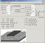
Hello all! Some time ago I used this online calculator: **broken link removed** (currently offline, but I have saved web page with calculator script). I noted that if all parameters kept constant then 50 ohm line width decreases with increasing frequency. Surprisingly linecalc tool in QUCS or ADS gives opposite result: 50 ohm line width increases with frequency.

For example: substrate thickness h=1mm, er=4.3.

Sphere.ne.jp calculator gives:
9mm at 5GHz
1.6mm at 10GHz

QUCS/ADS linecalc gives:
2mm at 5GHz
>2.2mm at 10GHz

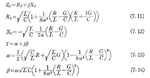
Linecalc gives line width similar to well-known formulas for calculating microstrip line impedance. But I am intrigued with sphere.ne.jp calculator, it seems have different approach. Which result is correct? Should line width increase or decrease with increasing frequency?
 

For example: substrate thickness h=1mm, er=4.3.

Sphere.ne.jp calculator gives:
9mm at 5GHz
1.6mm at 10GHz
The result is simply impossible for a microstrip. Either the calculator is scrap or you managed to operate it incorrectly.
 
FvM, sorry I posted incorrect value.
Correct values:
1)Sphere.ne.jp calculator gives:
1.9mm at 5GHz
1.6mm at 10GHz - decreased

2)QUCS/ADS linecalc gives:
2.0mm at 5GHz
2.2mm at 10GHz - increased

As you can see, line width is increased for 10GHz, which seems to be incorrect.
 

Attachments

  • 171030-210646.png
    171030-210646.png
    17.9 KB · Views: 218
  • 171030-210948.png
    171030-210948.png
    17.9 KB · Views: 163
  • 171030-211345.png
    171030-211345.png
    17.9 KB · Views: 286
Last edited:
Thank for your replies.
pancho_hideboo, for your example (substrate with h=0.2mm) sphere.ne.jp gives narrowest width at 100GHz. So maybe sphere.ne.jp gives wrong results:
1GHz 0.3596mm | on your wcalc image: 0.359
10GHz 0.358mm | on your wcalc image: 0.3587
100GHz 0.304mm | >>>> differs 0.4206mm

calculator available at archive.org:
https://web.archive.org/web/20160303231024/http://www1.sphere.ne.jp/i-lab/ilab/tool/ms_line_e.htm

sphere.ne.jp er=4.3 h=1mm
5GHz w=1.87 mm
10GHz w=1.79 mm
20GHz w=1.66 mm
40GHz w=1.53 mm
80GHz w=1.46 mm

wcalc and majority of calculators give the opposite result
5GHz w=1.91 mm
10GHz w=1.96 mm
20GHz w=2.18 mm
40GHz w=2.65 mm
80GHz w=3.01 mm

On a 1mm thick substrate difference is huge at 80GHz.

What about using FDTD to determine characteristic impedance?
For example, put quarterwave line of some width lineW between two 50-Ohm port terminations. Then analyze complex reflection coefficient on a smith chart. If reflection coefficient moved from center (50Ohm) to 200 Ohm, then line impedance was 100 Ohm (quarterwave matching Sqrt(50*200)=100).
 

wcalc gives same results as linecalc on Keysight ADS.

On a 1mm thick substrate difference is huge at 80GHz.
For such very high frequency, mode is not TEM any more.
So both results are not reliable.

What about using FDTD to determine characteristic impedance?
It is a fullwave analysis, so it is reliable than wcalc or similar tool.
https://www.awrcorp.com/products/additional-products/tx-line-transmission-line-calculator
 
1 mm substrate involves a cut-off frequency for non-TEM modes of about 70 GHz. Thus I presume, you don't actually want to use the strip line at 80 GHz and above.

By the way, what's the substrate material? Are you sure that the permittivity is fairly constant for the questioned frequency range?
 
Status
Not open for further replies.

Part and Inventory Search

Welcome to EDABoard.com

Sponsor

Back
Top