simha.nitc
Newbie level 4
Thanks in advance.
Can any tell me how to match analog circuits to 50 ohm line..
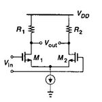
Lets say i have a differential buffer amplifier, and now i want to match the buffer to 50 ohm line. Effectively , gain=0dB, input impedance=100 ohm, output impedance=100 ohm and the Bandwidth is 100MHz.
Let me share the circuit too..
Can any tell me how to match analog circuits to 50 ohm line..
Lets say i have a differential buffer amplifier, and now i want to match the buffer to 50 ohm line. Effectively , gain=0dB, input impedance=100 ohm, output impedance=100 ohm and the Bandwidth is 100MHz.
Let me share the circuit too..