Continue to Site

Welcome to EDAboard.com

Welcome to our site! EDAboard.com is an international Electronics Discussion Forum focused on EDA software, circuits, schematics, books, theory, papers, asic, pld, 8051, DSP, Network, RF, Analog Design, PCB, Service Manuals... and a whole lot more! To participate you need to register. Registration is free. Click here to register now.

4x4 Keypad interfacing to PIC18f458

Status
Not open for further replies.

csr1981

Member level 2
Joined
May 10, 2005
Messages
52
Helped
1
Reputation
2
Reaction score
1
Trophy points
1,288
Location
India
Activity points
1,645
Hi,

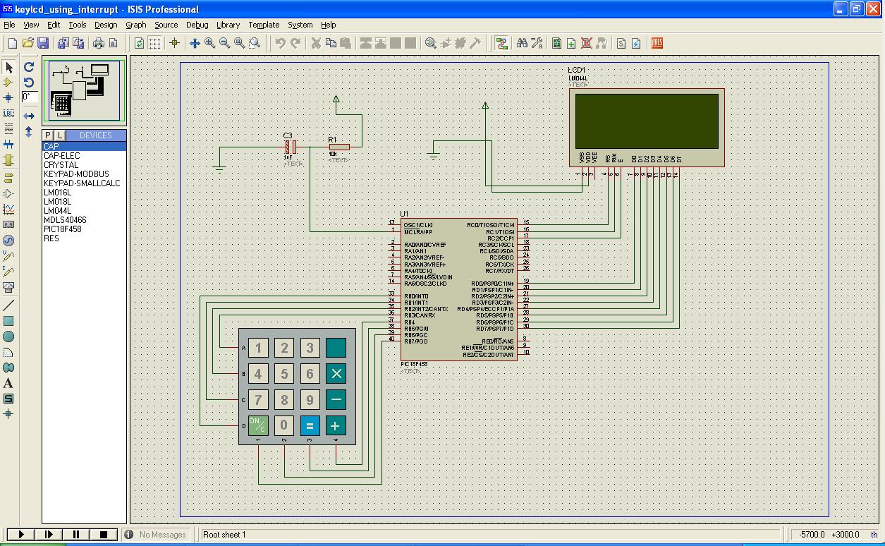
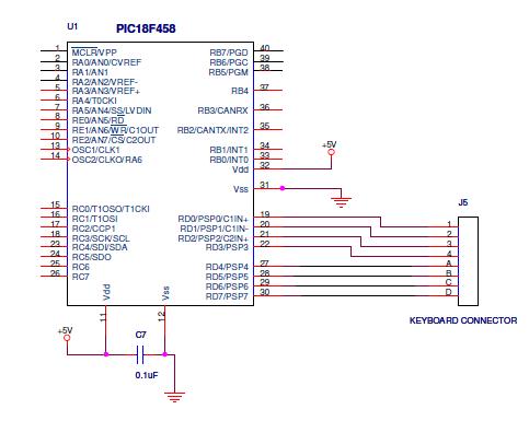
i want to inetrface a 4x4 keypad to PIC18f458.

I am using the below circuit but my code is not working.

15_1263875501.jpg


When i simulate in proteus it works but doesnot work in hardware.

Please help. If any c code is available, plz help with that also.

Thanks.
 

Hi csr1981,

How do you simulate using only a connector in place of the keypad? Please post your code so that we may help you.
 

Hi,
Keyboard connection
**broken link removed**
 

Hi,
In the circuit provided, you forgot to set MCLR pin high, so the microcontroller is in reset mode and not doing anything. Connect the MCLR pin to +5v with a resistor (about 10k) and try it.
Hope it helps.
Tahmid.
 

Hi Tahmid

i had just posted the part of my circuit. I have connected the MCLR pin to Vcc.
All other things are working fine.
Only the keypad is not working.
 

Hi,
Maybe you should pull-down RD0, RD1, RD2 and RD3 to ground with 10k resistors.
I do that when I use keypad.
Tahmid.
 

Tahmid said:
Hi,
Maybe you should pull-down RD0, RD1, RD2 and RD3 to ground with 10k resistors.
I do that when I use keypad.
Tahmid.

You don't need any external resistors.
Its not necessary. (depends ur code.)
 

Hi Tahmid,

Yes no problem, i can use mikroC.
Also if you can share the hardware ckt.

Thanks.
 

csr1981 said:
Hi Tahmid,

Yes no problem, i can use mikroC.
Also if you can share the hardware ckt.

Thanks.


If u have CCS compiler use the example program with it. There is diver available with CCS compiler called 'KBD.c'
c:\program files\picc\examples\ex_lcdkb.c

Ur circuit diagram is correct and no need to change it.


Good luck.
 

thanks for the input, but i donot have a CCS compiler.
 

Suggest you use active low logic. Output low on any of the 4 outputs and then look for low on the 4 inputs. You WILL need pullup resistors on the 4 inputs, internal weak pullups may be ok if the port has them, would go for external myself 1-10k ok, I tend to use 4K7.

Added after 6 minutes:

Simulation gives a good indication that a circuit may work, but this as in many cases it fails to take account of real world conditions. In theory you circuit should work, in practice not.

Added after 5 minutes:

This is 3x4. Maybe it will give you some ideas.

//Read Keypad and returns Digit Value

unsigned char GetKey(void)
{ // Get Keypress Active Low
unsigned char Digit, KeyRead;
C1 = 0; C2 = 1; C3 = 1; // Column 1 On
DelayMs(3);
KeyRead = (P2 & 0x0F);
if (KeyRead == 14) {Digit = 1;goto Skip;} // Read Rows and Translate
if (KeyRead == 13) {Digit = 4;goto Skip;}
if (KeyRead == 11) {Digit = 7;goto Skip;}
if (KeyRead == 7) {Digit = 10;goto Skip;} // Cancel Key

C1 = 1; C2 = 0; C3 = 1; // Column 2 On
DelayMs(3);
KeyRead = (P2 & 0x0F);
if (KeyRead == 14) {Digit = 2;goto Skip;}
if (KeyRead == 13) {Digit = 5;goto Skip;}
if (KeyRead == 11) {Digit = 8;goto Skip;}
if (KeyRead == 7) {Digit = 0;goto Skip;}

C1 = 1; C2 = 1; C3 = 0; // Column 3 On
DelayMs(3);
KeyRead = (P2 & 0x0F);
if (KeyRead == 14) {Digit = 3;goto Skip;}
if (KeyRead == 13) {Digit = 6;goto Skip;}
if (KeyRead == 11) {Digit = 9;goto Skip;}
if (KeyRead == 7) {Digit = 11;} // Call Key

Skip:
Blip();
DelayMs(30);
while ((P2 & 0x0F) != 0x0F);ResetWD(); // Wait for Key Release
return Digit;
}
 

Hi,
This is a sample code provided in mikroC v8.2:
Code:
unsigned short kp, cnt;
char txt[5];

void main() {
  cnt = 0;
  Keypad_Init(&PORTC);
  Lcd_Init(&PORTB);         // Initialize LCD on PORTC
  Lcd_Cmd(LCD_CLEAR);       // Clear display
  Lcd_Cmd(LCD_CURSOR_OFF);  // Cursor off

  Lcd_Out(1, 1, "Key  :");
  Lcd_Out(2, 1, "Times:");

  do {
    kp = 0;

    //--- Wait for key to be pressed
    do
      //--- un-comment one of the keypad reading functions
      kp = Keypad_Released();
      //kp = Keypad_Read();
    while (!kp);

    cnt++;

    //--- prepare value for output
    if (kp > 10)
      kp += 54;
    else
      kp += 47;

    //--- print it on LCD
    Lcd_Chr(1, 10, kp);
    WordToStr(cnt, txt);
    Lcd_Out(2, 10, txt);

  } while (1);
}//~!
Hope it helps.
Tahmid.
 

Hi, whay my PIC18F458 different with your in my proteus? I using Proteus 7.
Now i doing my assingment for this PIC18F458. Can you help me to draw the schematic using PROTEUS with the basic component required to run a PIC18F458. Thanks.
 

Hi thetravellerzt
the PIC18f458 i shown above in the circuit is the one drawn in OrCad.
 
Hello thetravellerzt

here is the ckt in Proteus


Status
Not open for further replies.

Similar threads

Part and Inventory Search

Welcome to EDABoard.com

Sponsor

Back
Top