Continue to Site

Welcome to EDAboard.com

Welcome to our site! EDAboard.com is an international Electronics Discussion Forum focused on EDA software, circuits, schematics, books, theory, papers, asic, pld, 8051, DSP, Network, RF, Analog Design, PCB, Service Manuals... and a whole lot more! To participate you need to register. Registration is free. Click here to register now.

4v regulated supply from 12v dc

Status
Not open for further replies.

mahesXtremeEngineering

Advanced Member level 4
Joined
Dec 17, 2011
Messages
103
Helped
2
Reputation
4
Reaction score
2
Trophy points
1,298
Activity points
1,832
how can i create a 4v(500mA-1A) regulated supply from a 12v dc.
How can it be implemented using a LM317.
 

Read here:
**broken link removed**

**broken link removed**

V out= 1.25 (1 +R2/R1) + Iadj * R2

Iadj = 50 - 100uA


To obtain V out= 4V and using R1= 240 ohms

we need to set for R2= 518- 522 ohms


;-)
 
Last edited:
Why not use a 7805 Regulator to get a regulated 5V from 12V Dc supply then use 2 resistors to make a voltage divider to drop one volt and get 4V stable supply???
 

''Stable power supply'' using two resistor voltage divider? C'mon... :roll:
By the way, can you consider what value resistors will provide the 1 Amp load? 8-O
 

@Qube

Let's test the voltage divider solution: :wink:
 

Attachments

  • load test 1.GIF
    load test 1.GIF
    16.4 KB · Views: 243
  • load test 2.GIF
    load test 2.GIF
    17.7 KB · Views: 176

i guess,it cant provide 1Amp current, or can it??
 

In post #2, mister_rf has provided everything you need to design the circuit with LM317.

However, you should know that, while the circuit is simple, it is very inefficient. At 4V 1A output, the efficiency is [(4*1)/(12*1)]*100% = 33.33%. So, you waste 2/3 of your input power / energy as heat. This will make the LM317 HOT! You will need to provide proper heatsinking to ensure you don't burn the LM317.

For a more efficient solution, you should use a switching regulator. A simple one is LM2575-ADJ. Datasheet: www.national.com/ds/LM/LM1575.pdf
You can find the circuit in page 12 of the datasheet.

Hope this helps.
Tahmid.

---------- Post added at 23:55 ---------- Previous post was at 23:53 ----------

For a stable output, you would need a buffer or power amplifier. You can not get stable output without the power amplifier stage due to the resistance of the load affecting the voltage divider.

Problem with 1A current supply would be that the voltage divider would dissipate too much wasted power.
 
As for original question: after reading 1st line I thought: "LM317". Then in 2nd line poster gives answer himself. Everything on how to use this IC is in the datasheet - don't people read datasheets anymore, or what? This is an electronics forum, right? Not a downtown audio / video store... :p

However, you should know that, while the circuit is simple, it is very inefficient. At 4V 1A output, the efficiency is [(4*1)/(12*1)]*100% = 33.33%. So, you waste 2/3 of your input power / energy as heat. This will make the LM317 HOT! You will need to provide proper heatsinking to ensure you don't burn the LM317.
Indeed, @ 1A that's (12-4V * 1A) = 8W, rather a big waste for a simple 1A regulated supply. Would require a decent size heatsink.

So you might consider a simple step-down switching regulator (like LM2575-ADJ) for this task, perhaps a bit more expensive but still easy to use, much more efficient & no need for a bulky heatsink.
 
RetroTechie #8

I was only familiar with LM317 which will do such job.

Thank you for introducing LM2575-ADJ.
 

Thank Tahmid - he mentioned it. :-D (although I knew these LM25xx series too).

Note that you will need a suitable coil to go with that switching regulator, and a Schottky rectifier diode like 1N5819 (see datasheet), 'any ordinary coil' (or diode!) won't do. I suggest you buy those parts in the same place, where they sell LM25xx series switching regulators they should also have suitable coils to go with them. And preferably low-ESR capacitors on input & output. :!:
 
Last edited:

What about connecting a 4v zener diode (not sure whether exact 4v is available) of high watt to the output of regulated 5v supply.
 

Do not overlook the idea of using a diode to subtract 0.7 volts or so from the 5V supply. Diodes are cheap and can handle the amps.

You can stack multiple diodes to obtain whatever drop you wish (as long as you can accept plus or minus .35 V deviation).

Is it important to get exactly 4V? Zeners are typically within a 5% tolerance of the nominal value. 3.9 is one of the standard values, and in reality may yield anywhere between 3.7 and 4.1V.

If you need exactly 4V, then it's probably best to go with an adjustable method.

I was talking about using the zener diode as a voltage regulator and taking the output across it.
5% tolerance is acceptable.
 

A 4 or 4.1 V zener can be used, since you say you can allow 5% variation.

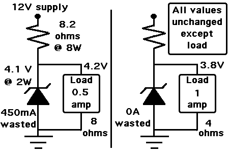
This schematic works in my simulator, providing 3.8 V to your heaviest stated load of 1 amp.
It provides 4.2V to your smaller load of 1/2 amp.

34_1331353053.gif


With no load connected, it consumes 1 amp as wasted power. The zener diode dissipates 4W.

There is no power wasted when a 1 amp load is connected. The zener diode is off.

There are two types of voltage regulation: (1) shunt regulation (zener diode) and (2) series regulation.
A series regulator can be more accurate and more efficient (and is recommended per the trend of replies here).
The choice as to which method to use is up to you.
 

A 4.7V zener can be used to drive a transistor configured as voltage follower. So, you get 4.7v-0.7v = 4.0v at the output. But, there is much less wasted power when load is zero or small as the zener is on only to provide a small current to the transistor which drives the load. However, this suffers the same problem as a linear regulator (which this also is) in terms of efficiency as this has only (4/12)*100% = 33.3% efficiency with a loss of 8*1 = 8W at 4V, 1A output.

Hope this helps.
Tahmid.
 

I am in full agreement with Tahmid. It is always better to have switching power supply at these currents. it would help not to waste power across the regulator.
 

Do you think simple series diodes will do the job??

one diode will have 0.6V drop,so 2 diodes in series with a input of 5V will regulate the voltage and give a output voltage of about 3.8V... Just my speculation....if i'm wrong,please correct me
 

If you have an input voltage of 5V, then you can use 2 diodes. Thing is, you won't always have 0.6V drop. It changes with current. Check the datasheet of the diode.

eg. Take a look at the 1N4007 datasheet from Fairchild. With a current of 1A, the forward voltage is 1.1V

Datasheet: www.fairchildsemi.com/ds/1N/1N4001.pdf

Just take a look at Figure 2 in page 2 of the datasheet and you'll get what I mean.

Hope this helps.
Tahmid.
 

the diodes , i fear would not have constant drop . all diodes wonr have same drop even though theoritically they expected to.

yes you canuse them. but dont expecte a fixed output
Best is to use LM1117-3.3 a LDO regu;lator which can do your job.or LM2940-3.3 or so.
 

@Tahmid and Sarma
yes,i see that,thanks for answering my doubt :)
so according to the datasheet for diode 1N4001,at 1A forward current,it has around 0.9V forward Voltage
 
Last edited:

Status
Not open for further replies.

Similar threads

Part and Inventory Search

Welcome to EDABoard.com

Sponsor

Back
Top