Continue to Site

Welcome to EDAboard.com

Welcome to our site! EDAboard.com is an international Electronics Discussion Forum focused on EDA software, circuits, schematics, books, theory, papers, asic, pld, 8051, DSP, Network, RF, Analog Design, PCB, Service Manuals... and a whole lot more! To participate you need to register. Registration is free. Click here to register now.

4-20mA to 0-3.3V current to voltage conversion

Status
Not open for further replies.

Switcher

Newbie level 5
Joined
May 2, 2015
Messages
8
Helped
0
Reputation
0
Reaction score
0
Trophy points
1
Activity points
68
If you find my posts helpful, please provide a like.

@Yolco, Schmitt trigger: Need your help
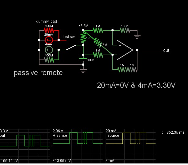
1) I am trying a similar circuit. What are your views on this. Would it work? (My main circuit has 3.3V dc)
2) To test this circuit on a breadboard, I do not have a transducer right now. What is a simple and effective way to make an Adjustable Constant Current Source?
(I am thinking of using an LM7805 in current limit mode.)

https://www.ti.com/lit/ds/symlink/tl064m.pdf
 

Attachments

  • Sheet1.pdf
    56.3 KB · Views: 219

Hi guys,Need your help:
An application requires me to convert 4-20 mA current signal from a pressurre transmitter to 0 to 3.3V signal for ADC of uC.
1) I have worked out a circuit (attachment). What are your views on this? Would it work?

I am using opamp TL062, but giving it a unipolar single supply (3.3V, GND). My main circuit already has 3.3V dc.
2) To test this circuit on a breadboard, I do not have a transducer right now. What is a simple and effective way to make an Adjustable Constant Current Source of 4 to 20mA?.

I am thinking of using an LM7805 in current limit mode.(I DO NOT have a dc supply in CC mode)
 

Attachments

  • Sheet1.pdf
    56.3 KB · Views: 232

hi.
This LTSpice sim shows the response of your proposed OPA.
It will give the required result.
E

EDITED:
Corrected sim!
Use a variable voltage source onto the 165R to give a 4 thru 20mA current

The only problem will be the TL062 output swing limit, use a rail to rail OPA eg: MCP6002
 

Attachments

  • AAesp03.gif
    AAesp03.gif
    30.5 KB · Views: 333
Last edited:
Thank you Esp1.

Just to confirm what you said:
1) The circuit will work if I use a rail to rail OPAMP like MCP6002.
Rather, can I use the same OPAMP (TL062) if I supply 5V and GND ? (Vref being 3.3V and rest of circuit remaining same)

2)To test on a breadboard, I can use an independent 24V dc supply (ground being common) and a pot between 24V dc and 165R. (6k/0.5W for 4mA; 1.2k/0.5W for 20mA) ?
 

With 5V supply, you still need an OP with output voltage range down to negative rail and common mode range down to 0.6V. TL062 doesn't work for this application, cheap LM358 e.g. would (but needs 5V supply to reach 3.3V).
 
Hi,

you are using an ADC, so you process the data somehow, maybe with a microcontroller.

Then i recoomend to use an input range with some headromm in both sides.
Maybe 0..24mA. Then 4..20mA is well within. No need to find the exact resistors. Software will adjust..

A simple subtract (offset) and multiply (gain) is necessary in software. You can easily adjust on OPAMP offset or resitor values/errors.

With this additionally can detect a broken sensor line (<4mA) or an overflow (>20mA).

I think it is generally not a good idea to go to the "limits". Not with an ADC input nor with an OPAMP output.
You will never know if 0V is really 4mA or ... is it 3mA?. The same is with the upper limit.

Klaus
 
Hi,

You could use a pair of LM334 adjustable current sources.
In my eyes the LM334 is more a temperature dependent current source than a constant current source.

Klaus
 
Klaus;
I don't dispute your statement...however, for the purposes of quick bench testing, where the ambient temperature will be relatively constant, it may be "close enough".
 
Thank you guys

I don't have LM334 right now. For a quick test, using a variable resistor in series with the 165R drawn from an isolated 24V. How accurate will the results be?
 

Hi

How accurate will the results be?

Of your current source or of your I-U converter?

Without current meter? Just the errors of the parts?

If you have a current meter, then use it. As long it is more reliable than the parts..

Klaus
 

Hi switcher,
Measure the voltage across the 165R resistor and use a calculator to work out the current.
You only need the two points, 4mA and 20mA.

V=165*0.004 =0.66v and the 20mA value.
E
 

With 5V supply, you still need an OP with output voltage range down to negative rail and common mode range down to 0.6V. TL062 doesn't work for this application, cheap LM358 e.g. would (but needs 5V supply to reach 3.3V).

@FvM: got your point. How did you infer input common mode range to be 0.6V from the datasheet?
I have to look at the Maximum peak output voltage swing and the input common mode voltage range, right?

Any compensation required for LM358?
MCP6002 has lesser input bias current and offset voltage. It is also cheaper. I think I'll go with that
 

To convert 4~20mA to 0~3.3V ...

Gain is 3.3V/16mA=206.25 for rail to rail OA( in+out)
use R=206 with unity non-inverting gain and Offset is 4mA*206R= (-) 824mV

Using 165R results in 660mV offset error at 4mA instead of 0V.

Or use inverting gain with + offset of 824mV offset down from Vref =3.3 or Vin(+)=2.476

Thus use R=206Ohms and gain = -1

You can also use OAs that do not have R-R input but have R-R output and use a smaller R, smaller offset and more OA gain.

This is just a quick and dirty solution; yours is inaccurate.

For a current source on sender, a 3 terminal LDO can be used as a CC source with R between Vref (e.g. 1.25V) where Iout=1.25/R and no ground connection.
 

Hi,

you are using an ADC, so you process the data somehow, maybe with a microcontroller.

Then i recoomend to use an input range with some headromm in both sides.
Maybe 0..24mA. Then 4..20mA is well within. No need to find the exact resistors. Software will adjust..

Klaus

Thanks.good idea. But wouldn't a buffer stage after the 165R resistor still be necessary?
 

Thanks Skyguy.
I need an accurate design but rcv420 is too complicated and coslty. A V to I converter is not the only thing in my circuit. I have taken points from it though which I will use.
 

Good stuff, inverting is easy with + ref offset and differential current sense with good balanced input CMRR. Then invert again using R-R type OA's only using precision V/2 matched R's. ..is one way, other is software.
 

Hi,

Thanks.good idea. But wouldn't a buffer stage after the 165R resistor still be necessary?

No, a resistor 120 ... 150 ohms should work.
You may add a capacitor in parallel to resistor as low pass filter.

Only if you don't want a 3.3v drop. Then use a lower value resistor and an amplifier.

Klaus
 

with total swing gains of 3.3V/16mA = 206.25Ω...
you can use 103.2 Ω (0.1% 100Ω & 3.2kΩ
x2 inverting gain.


Then benefit is not separate power & wires for current sink.
Single Op Amp design.
Depends mostly on R Ratios.
Accuracy depends on R value tolerances.
Uses Current sink referenced to Vcc = 3.3 as well as gain and offset.

This shows an error of 155uV error out of 3.3V ideal Vref. supply is idealistic.
9050423000_1430860909.jpg


What is your error budget? and reference error?

BASICALLY, When divider on Vin(+) = Vin(-) at max current =20mA, Vout=0.

You can move filter cap across current sense R and ensure supply is stable.
 

Status
Not open for further replies.

Similar threads

Part and Inventory Search

Welcome to EDABoard.com

Sponsor

Back
Top