Continue to Site

Welcome to EDAboard.com

Welcome to our site! EDAboard.com is an international Electronics Discussion Forum focused on EDA software, circuits, schematics, books, theory, papers, asic, pld, 8051, DSP, Network, RF, Analog Design, PCB, Service Manuals... and a whole lot more! To participate you need to register. Registration is free. Click here to register now.

Sine Wave Inverter Design Help

Status
Not open for further replies.

Okada

Banned
Joined
Jun 16, 2016
Messages
1,159
Helped
129
Reputation
252
Reaction score
129
Trophy points
63
Activity points
0
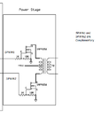
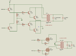
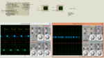
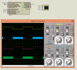
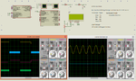
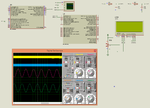
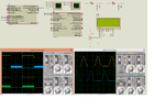
I am designing a Sine Wave Inverter using PIC16F1936. I have generated two signals with are complementary and I am getting Sine Wave from the two signals after RC filter in Proteus. Now I want to design the Power stage.

Can I design a power stage without output transformer that is using just MOSFETS ?

If yes, Should I use H-Bridge Topology ?

If not, then for a 5 or 5.25 KW Inverter what should be the transformer rating that is primary and secondary side V and I ratings.

Till now I have not checked other Inverter Circuits. I am new to Inverter circuit designing. I have only seen some PWM based (non SPWM) based inverters and they use power transistors or mosfets in parral to obtain required power in the output stage and also they use transformer.
 

This is related to Post #4 that is single phase SPWM Inverter. I don't know why mods merged this into 3 Phase Induction motor control thread. I was advised to post here and hence I am posting here.

I am attaching the circuit of the Inverter. There are two versions. Power transistor based and Power Mosfet based.

The 2N3773 VCE max is 140V and Continuous collector current is 16A.
The IRFP250 VDS max is 200 V and continuous Drain current is 30A.

Transformer is 84-0-84V Primary and 220V secondary.

To design a 5 or 5.25 KW Inverter what should be the current rating of the Primary and secondaries of the transformer ?

Lead Acid Batteries are used to get 24V for 7812 and 72V DC (6 12V Batteries in series) to the center tap of the transformer.

How many Power transistors or Mosfets should I use in each channel for a 5 or 5.25KW Inverter ?

Can I use a LC200C Charging circuit for charging the batteries with 2A charging current. That is can I charge all the 6 batteries with 2A charging current and charging connection in parallel with the batteries ?

The battery voltage is monitored using ADC and displayed on LCD.

I studied a little and found that a transformer is actually needed in an inverter because the primary side 168V will be stepped to 220V.
 

Attachments

  • swi.png
    swi.png
    30.4 KB · Views: 512

Hi,

still missing basics:

How do you think to get 84V (obviously RMS) out of a single 72V DC (battery voltage varying: 63V...83V?)

--> I´m off...


Klaus
 

Where did 63V came from ? 72V is incorrect. I have to use 7x 12V batteries in series to get 84V. DC is supplied to the center tap. The PWM signals to the two end connections of the transformer. The PWM will provide the switching voltages to the trf.

Where did my previous post went ? It did not appear. I said I attached the wrong image. Please make that post appear. I will change the image in that post.

RMS what ? You mean AC voltage ? Why should I provide AC RMS voltage to center tap of trf ?

This circuit I designed looking at some examples on the net. They were all tested circuits and they are working fine on hardware for more than 6 years. That's why I used those power output circuits.

Only PIC circuit is designed by me and and code is written to get 2 complementary SPWMs.

Please make my previous post appear. I asked a lot of questions in it.
 

All posts have been approved. Just a bit of patience.
 

In Post #12 I attached the wrong image. I am attaching the correct image here.

I am referring these two designs. One is PWM and another is SPWM based. I changed the PIC because I wrote a new code for the PIC and I also changed the PIC to PIC16F1936.

In my SPWM there are 128 points in half sine wave. So, my SPWM gives smooth sine wave. I am thinking abouth increasing the no. of points further.

PIC part is working fine. The problem is with Power stage designing.

My PIC circuit will use ADC to monitor battery voltage and display it on LCD. It will also show whether load is connected, battery is charging or not.

Should I use 7 adc channels to monitor each battery voltage or should I use 1 adc channel to monitor the 84V out of 7 batteries after scaling it down to 5V ?

I think monitoring each battery is good because if one battery is dead then it will be easier to find out which one is dead.
 

Attachments

  • Inverter.png
    Inverter.png
    41.3 KB · Views: 272

All posts related to the single phase 84 -> 230 V Inverter have been split to a separated thread.

Sorry for erroneously merging the first post into the other inverter thread.
 

Here are the 2 links I referred.

https://www.instructables.com/id/Adaptable-24vDC220vAC-Pure-Sinewave-Inverter-1/

https://www.instructables.com/id/250-to-5000-watts-PWM-DCAC-220V-Power-Inverter/

These are built and tested circuits. I have only changed the MCU. Later if PIC based works fine then I will use PIC32 or STM32 with TFT.

I think it is not good to use single L200C charging circuit to charge all the 7 batteries because if one battery voltage is 11.4V and another is 13.2V then the second battery will get overcharged while first one is charging.

I will go with individual L200C charging circuits for each battery and also each battery will be monitored separately using 7 adc channels.

Is 2A charging current enough for charging the 12V batteries ?
If yes, how much time it will take to charge the battery ?

What should be the Ah rating of the battey ?

I took the Power stage circuit of the PWM Inverter and used it with my SPWM generating PIC.

There are advantages and disadvantages of using power transistor and power mosfets like

If I use power transistors then as they are TO220 package I can easily mount them on the heat sink and solder thick wires between the parallel power transistors and this will save PCB space and also PCB track width related issue.

If I use Power mosfet then I have to put them on PCB and I want to know what should be the distance of each parallely connected mosfet on the heat sink so that heat is desipatted properly.

If mosfets are used then what should be the track width for the Drain and Source paths on the PCB. I will be using FR4 Glass Epoxy PCB.
 

For power transistor based circuit he says each transistor can provide 250W. The max Continuous collector current is 16A.

Is he calculating like this for 750W Inverter.

P = VI

I = P/V = 750/24 (battery voltage applied to center tap of trf)

= 31.25 A

The transistors should not be run at max ratings and hence 3 transistors are used in parallel so that collector current in each transistor will be

31.25/3 = 10.417A

For power mosfet for 5250W Inverter the max Drain Current is 30A for IRFP250.


So, I = P/V = 5250W / 84V = 62.5A

If each mosfet Drain current is made to be 10.417A then 6 mosfets are needed in each channel's power stage. Am I right ?

How to calculate power dessipated by the mosfet ?

P = VI = 84V * 10A = 840W ? but Mosfet max power is 190W.

Please explain this.

Also is this calculation right.

For transformer output stage for 5.25KW Inverter.

P = VI

I = P/V = 5250W/220V = 23.864A.

If 220V 25A secondary transformer is used then when load is full then current will be approx 23A which is close to max rating of the trf which is 25A. So the trf will die soon. So, Should I use a 220V 40A secondary transformer ?

Also what should be the current rating of the 84-0-84V primary side of the transformer ?

I have calculated backup time like this. Is this correct ?

If load is 2000W for a 5.25KW inverter then

Battery voltage is 84V and Ah is 60Ah.

Backup time = 84V * 60Ah / 2000W = 2.52 hours.

Is this right ?

Please answer as I have to build this soon and then I have to improve this design further.
 
Last edited:

So, I = P/V = 5250W / 84V = 62.5A

62,5 A is average battery current, theoretical value for an inverter with 100 % efficiency. If 5.25 kW is power of a sine inverter, the peak power will be double this value. The transistors must be rated for a respective peak current.

How to calculate power dessipated by the mosfet ?
P = VI = 84V * 10A = 840W ?
No. power dissipation is conduction losses plus switching losses.
 

Pulsed drain current for IRFP250 is 120A.

So, I = P/V = 5250W * 2 / 84V = 125 A

Max drain current of Mosfet is 30A. Assuming current through each mosfet to be 12.5A I have to use 10 parallel mosfet in each channel. So, I need 20 Mosfets. Right ?

- - - Updated - - -

In the transistor based circuit I forgot to put the diodes in the transformer primary. What diodes can I use for a 5250W Inverter. Actually I will not be building the power transistor version. I will be building the power mosfet version. Just to know I am asking which diode I can use.

Why can't I use a 12-0-12V primary to 220V 40A secondary step up transformer so that I can use only one 12V batterie of say 80Ah to get 5.25KW ?

- - - Updated - - -

I changed my mind a little. I am thinking of implementing a transformer less based SPWM Inverter. As this thread exists I am asking the new question here. If this is not proper then please move this new question to a new thread.

I am referring the attached document.

In that I am using IR2110 for a H-bridge inverter. Can I build a 5.25KW H-bridge Inverter which doesn't require a output step-up transformer ?

If yes,

Do I need just two SPWM signals which are complementary to each other to feed to the two IR2110 drivers ?

Same SPWM signal is fed to two N-Channel Mosfets.

If yes,

How to design required filters for the 5.25KW H-bridge transformerless inverter ?

What should be the current ratings of the toroidal inductors in the filters ?

What should be the Mosfet ratings ?

What should be the DC voltage provided to the drain of the Mosfet ?

How to get that DC ? by connecting 12V batteries in series ? If yes, how to do the calculation ?


I am still googling for a lot of information.

I think the transformer based Inverter will be costly as transformer for a 5.25KW Inverter will be costly and bulky.

Please answer questions related to both kinds of Inverters.
 

Attachments

  • MQP_D_1_2_2.pdf
    5.3 MB · Views: 328
Last edited:

Here I am making a fresh post. Please answer to this post in a single post.

This will be related to transformer less and transformer based Half-bridge and Full-Bridge H-Bridge Inverters.

I am really sorry, This post is lengthy.

What fast switching TVS diode can I use across Drain and Source of Mosfet's and what should be the current

rating of the diode for a full bridge 5.25 KW Inverter ?

Is these calculations correct ?

I am going to design a Full-Bridge SPWM Inverter of 5250W, 220V, 50Hz.

I will choose N-Channel Mosfets of Vds max = 600V and Continuous Drain Current of 40A.

I will be using IRFPS40N60K N channel Mosfet for the full bridge Inverter. It has Vds max = 600V and continuous

Drain current of 40A. It is a 570W Mosfet. It has an internal protection diode across Drain and Source.

Rds(on) at 10V GS voltage is 0.11

Is this a suitable Mosfet for 5.25 KW Inverter ?

Output P = VI

I = P/V = 5250 W * 2/220 V = approx 47 A.

47/2 = 23.5 A (2 mosfets in parallel in the bridge)

As it is a 40A Mosfet and my max current is 47 A, so I will allow 23.5A to flow through the mosfets and so it

will be working approx at 50% of the max rating which is 40A.

So, I use two mosfets in parallel in the full bridge ? That is 8 Mosfets in total for a 5.25 KW Inverter ?

Or should I consider this

continuous Drain current at 25 degree C is 40A
continuous Drain current at 100 degree C is 24 A

Considering temperature of mosfets to be 100 degree C and to use it at 50% of max rating (24 A)
I have to make current through each mosfet to be 11.75 A and so I need 4 mosfets in parallel in the H-Bridge

with a total of 4 x 4 = 16 Mosfets ?


For a 220V Inverter what should be the Voltage applied to the Drain of the 2 top Mosfets of the full-bridge,

H-bridge Inverter and to the Source of bottom 2 Mosfets ? 220V/2 = 110V DC and -110V DC ?

The battery backup calculation is like this

output load is 2 KW
Voltage applied to Drains of the top 2 Mosfets of the full bridge = 240V DC (20x 12V batteries in series)
Ah of Battery = 60 Ah

backup time = 240V * 60Ah / 2KW = 7.2 hours

Is this right ?

If this is correct then this design needs a lot of batteries and the cost increases. How to reduce the cost ?

The earlier output transformer based Inverter needed less batteries and so the cost was less. It needed 7

batteries (84V DC).

For the full bridge system I want to design LC filter.

Formula is fc = 1/sqrt(2*Pi*LC)

My full bridge PWM is 50 KHz. What should be the cut-off frequency because I read somewhere that cut-off

frequency can be much lower compared to PWM frequency.

In a 40 KHz PWM design he chose cut-off frequency of approx 7 KHz.

I am attaching the document that I have referred. It is for a half bridge Inverter but for filter design I

choose the same filter calculation method for the full bridge Inverter.

The inductor and capacitor will be in series and the load will be in parallel to capacitor.

for 50 KHz PWM signal, lets say I chose cut-off frequency of 12 KHz (for a 50 Hz 220V sine wave Inverter)

Then 12 KHz = 1/sqrt(2*Pi*LC)

I will choose capacitor of 2.2uF 400V MKT.

So, L = 1/(4 * pi^2 * 2.2u^2 * 12K^2) = 1/(39.476089 * 0.00000000000484 * 144000000)

= 0.02751325498944 H

= approx 28 mH

Is this correct ? That is 2.2uF 400V MKT capacitor and 28 mH 40A toroidal inductor on powder iron core ?

If it is correct, can I get such an inductor for a 5.25KW full bridge inverter ?

What should be the current rating of the capacitor ?

In Proteus I see 3A polarized Capacitors but I will be using Metallized Poly Propylene Capacitors.

In the PIC datasheet PWM section it actually shows a FET driver between PIC and H-bridge Mosfets.

Please, I am new to inverter design and I am trying to find out which is cheaper

push-pull type transformer based SPWM inverter or
Half bridge transformer less Inverters or
Full bridge transformer less inverters

I will build the one which will be cheaper.

For a Half bridge system 1x IR2110 FET driver can be used but for full bridge system can I use 2x IR2110 ?

If I am doing some thing wrong then please correct me.

To*minimize power*loss*and*utilize*higher*switching*speeds,*N*Channel*MOSFETs are used in the H-bridge of

half-bridge and full-bridge systems. Also for high output currents N-Channel MOSFETS are used. Right ?

I am referring to these two links

https://tahmidmc.blogspot.in/2012/10/generation-of-sine-wave-using-spwm-in_10.html

https://tahmidmc.blogspot.in/2013/02/sine-wave-generation-with-fast-pwm-mode_2525.html

See my Proteus simulation image. I am not getting proper PWM signals ? Why ?

I am also referring this for LC filter for the H-Bridge Inverter

https://www.edaboard.com/threads/318361/

I assume L and C are in series. My PWM freq is 50 KHz and 220 V frequency is 50 Hz and minimum load is 9W. How

can I calculate L and C values ?


PIC datasheet says this.

The Full-Bridge mode does not provide dead-band
delay. As one output is modulated at a time, dead-band
delay is generally not required. There is a situation
where dead-band delay is required. This situation
occurs when both of the following conditions are true:
1. The direction of the PWM output changes when
the duty cycle of the output is at or near 100%.
2. The turn off time of the power switch, including
the power device and driver circuit, is greater
than the turn on time.

In my design the Toff delay (97 ns) is greater than Ton delay (47 ns) for Mosfet
For IR2110 the Toff delay (94 ns) is less than Ton delay (120 ns)

In the attached image you can see that signals change polarity when PWM duty is max

So, should I implement dead band elimination in code or not ? Actually I have implemented it but not sure if it

is needed or not in my case.

I have implemented like this.

max PWM duty is 255 (100 %) and PWM freq is 50 KHz and so PWM period = 1/50 KHz = 20 us and so in code if pwm

duty is 255 then I skip 8 interrupt and update the required variables. So, in my sine table each value is

repeated 8 times and so for 8 * 20 us = 160 us the PWM signals are turned off. Is this proper way of

eliminating the dead band or should I just skip the last 20 us of the 8 * 20 us delays that is

if pwm duty is 255 then use a counter and count 7 times with applying pwm duty and updating the required

variables in the ISR when counter is 7 skip applying pwm duty to CCPR1L and update the other variables in the

ISR in the else condition in the below ISR code ?

This is my code.


Code C - [expand]
1
2
3
4
5
6
7
8
9
10
11
12
13
14
15
16
17
18
19
20
21
22
23
24
25
26
27
28
29
30
31
32
33
34
35
36
37
38
39
40
41
42
43
44
45
46
47
48
49
50
51
52
53
54
55
56
57
58
59
60
61
62
63
64
65
66
67
68
69
70
71
72
73
74
75
76
77
78
79
80
81
82
83
84
85
86
87
88
89
90
91
92
93
94
95
96
97
98
99
100
101
102
103
104
105
106
107
108
109
110
#define NUMBER_OF_TABLE_ENTRIES_FOR_180_DEGREES 64
#define FACTOR_TO_GET_360_DEGREES
 
char i = 0;
 
unsigned int sin_table[64] = {128,140,152,165,176,188,198,208,
                              218,226,234,240,245,250,253,254,
                              255,254,253,250,245,240,234,226,
                              218,208,198,188,176,165,152,140,
                              128,115,103,90,79,67,57,47,
                              37,29,21,15,10,5,2,1,
                              0,1,2,5,10,15,21,29,
                              37,47,57,67,79,90,103,115
                             };
 
unsigned int TBL_POINTER_NEW, TBL_POINTER_OLD, TBL_POINTER_SHIFT, SET_FREQ = 410;
char DUTY_CYCLE = 0;
 
//Timer2
//Prescaler 1:1; Postscaler 1:1; TMR2 Preload = 97; Actual Interrupt Time : 19.6 us
//Place/Copy this part in declaration section
void InitTimer2(){
    T2CON = 0x04;
    PR2 = 97;
    TMR2IE_bit = 1;
    INTCON = 0xC0;
}
 
void interrupt(){
 
    if(TMR2IF_bit) {
 
        TMR2IF_bit = 0;
        
        if(sin_table[DUTY_CYCLE] != 255) { 
            TBL_POINTER_NEW = TBL_POINTER_OLD + SET_FREQ;
            if (TBL_POINTER_NEW < TBL_POINTER_OLD) {
                   CCP1CON.P1M1 = ~CCP1CON.P1M1;
            }
            TBL_POINTER_SHIFT = TBL_POINTER_NEW >> 10;
            DUTY_CYCLE = TBL_POINTER_SHIFT;
            CCPR1L = sin_table[DUTY_CYCLE];
            TBL_POINTER_OLD = TBL_POINTER_NEW;
        }
        else { //To eliminate dead band
            /*
            If changing PWM direction at high duty cycle is required
            for an application, two possible solutions for eliminating
            the shoot-through current are:
            1. Reduce PWM duty cycle for one PWM period
               before changing directions.
            2. Use switch drivers that can drive the switches off
               faster than they can drive them on.
            */
 
            TBL_POINTER_NEW = TBL_POINTER_OLD + SET_FREQ;
            TBL_POINTER_SHIFT = TBL_POINTER_NEW >> 10;
            DUTY_CYCLE = TBL_POINTER_SHIFT;
            TBL_POINTER_OLD = TBL_POINTER_NEW;
        }
    }
}
 
double map(double x, double in_min, double in_max, double out_min, double out_max) {
    return (x - in_min) * (out_max - out_min) / (in_max - in_min) + out_min;
}
 
void main() {
 
     Delay_ms(200);
 
     ANSELA = 0x00;
     ANSELB = 0x00;
 
     CM1CON0 = 0x00;
     CM2CON0 = 0x00;
 
     TRISA = 0xC1;
     TRISB = 0x00;
     TRISC = 0x00;
 
     PORTA = 0x00;
     PORTB = 0x00;
     PORTC = 0x00;
 
     LATA = 0x00;
     LATB = 0x00;
     LATC = 0x00;
 
     TBL_POINTER_SHIFT = 0;
     TBL_POINTER_NEW = 0;
     TBL_POINTER_OLD = 0;
     DUTY_CYCLE = 0;     
 
     PWM1_Init(50000);
 
     PWM1_Set_Duty(0);
 
     CCP1CON.P1M0 = 1;
     CCP1CON.P1M1 = 0;
 
     InitTimer2();
     
     PWM1_Start();
 
     while(1) {
     
 
     }
}


In this circuit he is using a transformer in the H-bridge.

https://www.homemade-circuits.com/2013/05/full-bridge-1-kva-inverter-circuit.html

and providing 12V to the Mosfets to get 220V

So, can I just use 1x or 2x 12V 120Ah battery to get 12V or 24V for the mosfets and use a transformer (0-12V or

0-24V - 220V 40 A secondary) to get 220V 5.25 KW 50 Hz full bridge Inverter ?

If yes, then how to calculate the output power of the Inverter ?

If this can be dome then it saves the cost of batteries.

Further by referring slaa602.pdf it shows that multiple parallel mosfets can be used in the H-Bridge to get

required output power and also the voltage to the mosfets can be 12V and using a transformer we can get 220V.

So, how to do the transformer calculation and how to calculate power of inverter ?

The slaa_602.pdf mentions to use 12V 150 Ah battery with output transformer in the H-Bridge to get 220 V. It

uses CSD18502 NexFet Mosfets. The Vds max = 40V and Id max at 100 degree C is 150 A

So, How to calculate how many parallel Mosfets I need in the H-Bridge for a 5.25 KW Full-Bridge Inverter ?

Can I use 2x IR2110 with CSD18502 NexFets or CSD18532KCS Mosfets ?
 

Attachments

  • Full Bridge, H-Bridge SPWM Inverter.png
    Full Bridge, H-Bridge SPWM Inverter.png
    198.8 KB · Views: 365
  • MQP_D_1_2_2.pdf
    5.3 MB · Views: 259
  • PWM_Techniques_final.pdf
    3.7 MB · Views: 260
  • slaa602.pdf
    1.6 MB · Views: 236
Last edited:

How about using

UCC27211
IRS21867SPbf

High side and Low Side Drivers ?

How about using RFP50N06 or FQP50N06 N-Channel Mosfets ?

What is the 380V DC mentioned in page no. 7 and 8 of sprabw0b.pdf ? Is it a voltage used for transformer less full-bridge Inverter ? From where he is getting 380V DC 380 V DC ? If it is for transforme less Inverter than why he has used transformer in page 15 ? He is only using 1x 12V battery.

--------------------------------------------------------------------------------------------------------------
The Vout of IRS21867S is 10 - 20 V. So, can I connect FQP50N06 Mosfet's Gate directly to HO and LO pins of IRS21867S ? I will be using 10V from IRS21867S for the Vgs of FQP50N06. FQP50N06 max VGS is +/- 25V and also its Rds(on) is 0.022 Ohms. Is it good to use low Rds(on) Mosfets for the Inverter ?

---------------------------------------------------------------------------------------------------------------
In the en.CD00201961.pdf page no. 24 what is the Voltage applied to the Drain of the IGBT ? It looks like a transforme less full-bridge Inverter. Also which is the DC-DC converter section which is providing the high voltage and what is the value of the voltage ?


This is my new code. Only code in ISR is modified to remove dead band. See image. Is the SPWM full bridge signals correct ?

Crystal is 20 MHz. Check the attached Proteus simulation. Thw SPWM signals are shuttling a little.

I have referred these pages.

https://tahmidmc.blogspot.in/2013/02/demystifying-use-of-table-pointer-in.html

https://tahmidmc.blogspot.in/2012/10/generation-of-sine-wave-using-spwm-in_10.html

https://tahmidmc.blogspot.in/2013/02/sine-wave-generation-with-fast-pwm-mode_2525.html


Code C - [expand]
1
2
3
4
5
6
7
8
9
10
11
12
13
14
15
16
17
18
19
20
21
22
23
24
25
26
27
28
29
30
31
32
33
34
35
36
37
38
39
40
41
42
43
44
45
46
47
48
49
50
51
52
53
54
55
56
57
58
59
60
61
62
63
64
65
66
67
68
69
70
71
72
73
74
75
76
77
78
79
80
81
82
83
84
85
86
87
88
89
90
91
92
93
94
95
96
97
98
99
100
101
102
103
104
105
106
107
108
109
110
111
112
113
char i = 0;
 
unsigned int sin_table[128] = { 512,537,562,587,611,636,660,684,
                                707,730,753,774,796,816,836,855,
                                873,890,907,922,937,950,963,974,
                                984,993,1001,1008,1013,1017,1021,1022,
                                1023,1022,1021,1017,1013,1008,1001,993,
                                984,974,963,950,937,922,907,890,
                                873,855,836,816,796,774,753,730,
                                707,684,660,636,611,587,562,537,
                                512,486,461,436,412,387,363,339,
                                316,293,270,249,227,207,187,168,
                                150,133,116,101,86,73,60,49,
                                39,30,22,15,10,6,2,1,
                                0,1,2,6,10,15,22,30,
                                39,49,60,73,86,101,116,133,
                                150,168,187,207,227,249,270,293,
                                316,339,363,387,412,436,461,486
                             };                                                          
                              
unsigned int TBL_POINTER_NEW, TBL_POINTER_OLD, TBL_POINTER_SHIFT, SET_FREQ = 128;
char DUTY_CYCLE = 0;
 
//Timer2
//Prescaler 1:1; Postscaler 1:1; TMR2 Preload = 97; Actual Interrupt Time : 19.6 us
//Place/Copy this part in declaration section
void InitTimer2() {
    T2CON = 0x04;
    PR2 = 97;
    TMR2IE_bit = 1;
    INTCON = 0xC0;
}
 
void interrupt(){
 
    if(TMR2IF_bit) {
        TMR2IF_bit = 0;       
        
        if(sin_table[DUTY_CYCLE] == 1023) { 
              TBL_POINTER_NEW = TBL_POINTER_OLD + SET_FREQ;
              if (TBL_POINTER_NEW < TBL_POINTER_OLD) {
                     CCP1CON.P1M1 = ~CCP1CON.P1M1;
              }
              TBL_POINTER_SHIFT = TBL_POINTER_NEW >> 9;
              DUTY_CYCLE = TBL_POINTER_SHIFT;
              CCP1CON.DC1B1 = 0;
              CCP1CON.DC1B0 = 0;
              CCPR1L = 0;
              TBL_POINTER_OLD = TBL_POINTER_NEW;                   
        }
        else if(sin_table[DUTY_CYCLE] != 1023) { 
              TBL_POINTER_NEW = TBL_POINTER_OLD + SET_FREQ;
              if (TBL_POINTER_NEW < TBL_POINTER_OLD) {
                     CCP1CON.P1M1 = ~CCP1CON.P1M1;
              }
              TBL_POINTER_SHIFT = TBL_POINTER_NEW >> 9;
              DUTY_CYCLE = TBL_POINTER_SHIFT;
              CCP1CON.DC1B1 = (sin_table[DUTY_CYCLE] & 0b00000010) >> 1;
              CCP1CON.DC1B0 = (sin_table[DUTY_CYCLE] & 0b00000001);
              CCPR1L = (sin_table[DUTY_CYCLE] & 0b11111100) >> 2;
              TBL_POINTER_OLD = TBL_POINTER_NEW;                 
        }       
    }
}
 
void main() {
 
     Delay_ms(200);
 
     ANSELA = 0x00;
     ANSELB = 0x00;
 
     CM1CON0 = 0x00;
     CM2CON0 = 0x00;
 
     TRISA = 0xC0;
     TRISB = 0x00;
     TRISC = 0x00;
 
     PORTA = 0x00;
     PORTB = 0x00;
     PORTC = 0x00;
 
     LATA = 0x00;
     LATB = 0x00;
     LATC = 0x00;
 
     TBL_POINTER_SHIFT = 0;
     TBL_POINTER_NEW = 0;
     TBL_POINTER_OLD = 0;
     DUTY_CYCLE = 0;     
 
     PWM1_Init(51020);
 
     PWM1_Set_Duty(0);
 
     CCP1CON.CCP1M3 = 1;
     CCP1CON.CCP1M2 = 1;
     CCP1CON.CCP1M1 = 0;
     CCP1CON.CCP1M0 = 0;
     
     CCP1CON.P1M0 = 1;
     CCP1CON.P1M1 = 0;
 
     InitTimer2();
     
     PWM1_Start();
 
     while(1) {
     
 
     }
}


Attachments

  • Correct SPWM.png
    Correct SPWM.png
    94.9 KB · Views: 185
  • en.CD00201961.pdf
    3.1 MB · Views: 259
  • sprabw0b.pdf
    358.1 KB · Views: 194
  • Sine Wave PWM Inverter Full Bridge, H-Bridge and Transformerless.rar
    18.9 KB · Views: 156
Last edited:

Asking so many different questions in one or two posts makes it unlikely to get them all answered at once. It's probably better to ask one-by-one.

What is the 380V DC mentioned in page no. 7 and 8 of sprabw0b.pdf ? Is it a voltage used for transformer less full-bridge Inverter ? From where he is getting 380V DC 380 V DC ? If it is for transformer less Inverter than why he has used transformer in page 15 ? He is only using 1x 12V battery.

I believe the paper explains the topology well with a block diagram. You have a 12-to-380 VDC isolating DC/DC converter using a high frequency transformer. And the said transformerless output stage. It's the preferred topology for compact battery inverters and is used e.g. in most recent UPS. The paper mentions a rated power of 100 W for the reference design. You'll probably use a higher battery voltage for higher powers than e.g. 500 W.

The selected 380 VDC seems to be chosen for wider voltage range (up to +15%) when operating the design as a grid-tied inverter as mentioned somewhere in the document, 325 VDC plus a small margin would be sufficient for 230 VAC output.

Your SPWM simulation waveform seems to use a simplified switching scheme where only one transistor is switched with PWM frequency at a time. The scheme has the disadvantage that it can't maintain a sine waveform in presence of reactive loads which already shows when an open circuit LC output filter is connected.
 

@FvM

So, should I generate 4 SPWM signals two of which are complementary and switch each diagonal Mosfets at a time with two complementary signals ?

Please check the attached Proteus simulations. Crystal is 8 MHz with 4x PLL = 32 MHz for PIC18F26K22. PIC18F26K22 is used for SPWM and PIC18F46K22 is used for LCD and ADC.

Are the generated signals correct ?

I am also posting the images so that people who don't have Proteus can have a look.

Calculations for SPWM

//Interrupt occurs once every 9.75 us (frequency is 1/t = 102.564 KHz
//Sine table is for 180 degrees
//1024 values for 180 degrees (2048 points for full Sine Wave)
//9.75 us * 1024 = 9.984 ms
//for full wave 9.984 * 2 = 19.968 ms
//F = 1/T = 1/19.968 ms = 50.08 Hz approx 50 Hz (Sine Wave frequency)

Are these correct ? especially the SPWM frequency.


I am planning to use these components for Full-Bridge Output Signals Driving a H-Bridge with Output transformer. Is my selction of components good ?
I have chosen Mosfets with low Rds(on)

I will use 2x 12V 150 Ah batteries in parallel.

BUK9520 N-Channel TrenchMOS Logic Level FET 100 V 100A Rds on 22m Ohms (NXP)
IRS21867S High and Low side Driver 2x

I am referring this link for Output Transformer design.

https://tahmidmc.blogspot.in/2012/12/ferrite-transformer-turns-calculation.html

What should be the current ratings of the Pri and Sec windings of the transformer for 5.25KW Inverter ?

@FvM

So, should I generate 2 SPWM signals which are complementary and switch each diagonal Mosfets at a time with same signals ? i.e., SPWM1 and SPWM2 are complementary and I use SPWM1 to switch diagonally opposite Mosfets with SPWM1 and another diagonally oppostte Mosfets with SPWM2. Only one set of diagonal Mosfets will be ON at a time. But this will be Half-Bridge Signals driving a H-Bridge or Full-Bridge Output. What SPWMx Signals I need to make a Full-Bridge Output Signals driving a H-Bridge or Full-Bridge Output ?


This is the code for Full-Bridge Signals Driving a H-Bridge/Full-Bridge Output. Is the code correct ? How can I improve this ?


Code C - [expand]
1
2
3
4
5
6
7
8
9
10
11
12
13
14
15
16
17
18
19
20
21
22
23
24
25
26
27
28
29
30
31
32
33
34
35
36
37
38
39
40
41
42
43
44
45
46
47
48
49
50
51
52
53
54
55
56
57
58
59
60
61
62
63
64
65
66
67
68
69
70
71
72
73
74
75
76
77
78
79
80
81
82
83
84
85
86
87
88
89
90
91
92
93
94
95
96
97
98
99
100
101
102
103
104
105
106
107
108
109
110
111
112
113
114
115
116
117
118
119
120
121
122
123
124
125
126
127
128
129
130
131
132
133
134
135
136
137
138
139
140
141
142
143
144
145
146
147
148
149
150
151
152
153
154
155
156
157
158
159
160
161
162
163
164
165
166
167
168
169
170
171
172
173
174
175
176
177
178
179
180
181
182
183
184
185
186
187
188
189
190
191
192
193
194
195
196
197
198
199
200
201
202
203
204
205
206
207
208
209
210
211
212
213
214
215
216
217
218
219
220
221
222
223
224
225
226
227
228
unsigned int sin_table[1024] = {512,515,518,521,524,527,530,533,
                                537,540,543,546,549,552,555,559,
                                562,565,568,571,574,577,580,583,
                                587,590,593,596,599,602,605,608,
                                611,614,617,621,624,627,630,633,
                                636,639,642,645,648,651,654,657,
                                660,663,666,669,672,675,678,681,
                                684,687,690,693,696,699,701,704,
                                707,710,713,716,719,722,725,727,
                                730,733,736,739,741,744,747,750,
                                753,755,758,761,764,766,769,772,
                                774,777,780,782,785,788,790,793,
                                796,798,801,803,806,809,811,814,
                                816,819,821,824,826,829,831,834,
                                836,838,841,843,846,848,850,853,
                                855,857,860,862,864,866,869,871,
                                873,875,878,880,882,884,886,888,
                                890,893,895,897,899,901,903,905,
                                907,909,911,913,915,917,919,920,
                                922,924,926,928,930,931,933,935,
                                937,939,940,942,944,945,947,949,
                                950,952,953,955,957,958,960,961,
                                963,964,966,967,968,970,971,973,
                                974,975,977,978,979,980,982,983,
                                984,985,986,988,989,990,991,992,
                                993,994,995,996,997,998,999,1000,
                                1001,1002,1003,1004,1004,1005,1006,1007,
                                1008,1008,1009,1010,1011,1011,1012,1013,
                                1013,1014,1014,1015,1015,1016,1017,1017,
                                1017,1018,1018,1019,1019,1020,1020,1020,
                                1021,1021,1021,1021,1022,1022,1022,1022,
                                1022,1023,1023,1023,1023,1023,1023,1023,
                                1023,1023,1023,1023,1023,1023,1023,1023,
                                1022,1022,1022,1022,1022,1021,1021,1021,
                                1021,1020,1020,1020,1019,1019,1018,1018,
                                1017,1017,1017,1016,1015,1015,1014,1014,
                                1013,1013,1012,1011,1011,1010,1009,1008,
                                1008,1007,1006,1005,1004,1004,1003,1002,
                                1001,1000,999,998,997,996,995,994,
                                993,992,991,990,989,988,986,985,
                                984,983,982,980,979,978,977,975,
                                974,973,971,970,968,967,966,964,
                                963,961,960,958,957,955,953,952,
                                950,949,947,945,944,942,940,939,
                                937,935,933,931,930,928,926,924,
                                922,920,919,917,915,913,911,909,
                                907,905,903,901,899,897,895,893,
                                890,888,886,884,882,880,878,875,
                                873,871,869,866,864,862,860,857,
                                855,853,850,848,846,843,841,838,
                                836,834,831,829,826,824,821,819,
                                816,814,811,809,806,803,801,798,
                                796,793,790,788,785,782,780,777,
                                774,772,769,766,764,761,758,755,
                                753,750,747,744,741,739,736,733,
                                730,727,725,722,719,716,713,710,
                                707,704,701,699,696,693,690,687,
                                684,681,678,675,672,669,666,663,
                                660,657,654,651,648,645,642,639,
                                636,633,630,627,624,621,617,614,
                                611,608,605,602,599,596,593,590,
                                587,583,580,577,574,571,568,565,
                                562,559,555,552,549,546,543,540,
                                537,533,530,527,524,521,518,515,
                                512,508,505,502,499,496,493,490,
                                486,483,480,477,474,471,468,464,
                                461,458,455,452,449,446,443,440,
                                436,433,430,427,424,421,418,415,
                                412,409,406,402,399,396,393,390,
                                387,384,381,378,375,372,369,366,
                                363,360,357,354,351,348,345,342,
                                339,336,333,330,327,324,322,319,
                                316,313,310,307,304,301,298,296,
                                293,290,287,284,282,279,276,273,
                                270,268,265,262,259,257,254,251,
                                249,246,243,241,238,235,233,230,
                                227,225,222,220,217,214,212,209,
                                207,204,202,199,197,194,192,189,
                                187,185,182,180,177,175,173,170,
                                168,166,163,161,159,157,154,152,
                                150,148,145,143,141,139,137,135,
                                133,130,128,126,124,122,120,118,
                                116,114,112,110,108,106,104,103,
                                101,99,97,95,93,92,90,88,
                                86,84,83,81,79,78,76,74,
                                73,71,70,68,66,65,63,62,
                                60,59,57,56,55,53,52,50,
                                49,48,46,45,44,43,41,40,
                                39,38,37,35,34,33,32,31,
                                30,29,28,27,26,25,24,23,
                                22,21,20,19,19,18,17,16,
                                15,15,14,13,12,12,11,10,
                                10,9,9,8,8,7,6,6,
                                6,5,5,4,4,3,3,3,
                                2,2,2,2,1,1,1,1,
                                1,0,0,0,0,0,0,0,
                                0,0,0,0,0,0,0,0,
                                1,1,1,1,1,2,2,2,
                                2,3,3,3,4,4,5,5,
                                6,6,6,7,8,8,9,9,
                                10,10,11,12,12,13,14,15,
                                15,16,17,18,19,19,20,21,
                                22,23,24,25,26,27,28,29,
                                30,31,32,33,34,35,37,38,
                                39,40,41,43,44,45,46,48,
                                49,50,52,53,55,56,57,59,
                                60,62,63,65,66,68,70,71,
                                73,74,76,78,79,81,83,84,
                                86,88,90,92,93,95,97,99,
                                101,103,104,106,108,110,112,114,
                                116,118,120,122,124,126,128,130,
                                133,135,137,139,141,143,145,148,
                                150,152,154,157,159,161,163,166,
                                168,170,173,175,177,180,182,185,
                                187,189,192,194,197,199,202,204,
                                207,209,212,214,217,220,222,225,
                                227,230,233,235,238,241,243,246,
                                249,251,254,257,259,262,265,268,
                                270,273,276,279,282,284,287,290,
                                293,296,298,301,304,307,310,313,
                                316,319,322,324,327,330,333,336,
                                339,342,345,348,351,354,357,360,
                                363,366,369,372,375,378,381,384,
                                387,390,393,396,399,402,406,409,
                                412,415,418,421,424,427,430,433,
                                436,440,443,446,449,452,455,458,
                                461,464,468,471,474,477,480,483,
                                486,490,493,496,499,502,505,508
                             };                                                          
 
unsigned int index = 0;
unsigned char myFlags = 0;
 
sbit change_direction_flag at myFlags.B0;
                             
//Timer1
//Prescaler 1:1; TMR1 Preload = 65497; Actual Interrupt Time : 9.75 us
//Place/Copy this part in declaration section
void InitTimer1() {
    T1CON = 0x01;
    TMR1IF_bit = 0;
    TMR1H = 0xFF;
    TMR1L = 0xD9;
    TMR1IE_bit = 1;
    INTCON = 0xC0;
}
 
void interrupt(){
 
    //Interrupt occurs once every 9.75 us
    //Sine table is for 180 degrees
    //1024 values
    //9.75 us * 1024 = 9.984 ms
    //for full wave 9.984 * 2 = 19.968 ms
    //F = 1/T = 1/19.968 ms = 50.08 Hz approx 50 Hz
    
    if (TMR1IF_bit){ 
        TMR1IF_bit = 0;
        TMR1H = 0xFF;
        TMR1L = 0xD9;
        //Enter your code here        
        
        //PWM duty is 10 bit
        //2 LSBs of PWM duty                
        CCP1CON.DC1B1 = (sin_table[index] & 0x02) >> 1;
        CCP1CON.DC1B0 = (sin_table[index] & 0x01);
        //8 MSBs of PWM duty
        CCPR1L = (sin_table[index] & 0b1111111100) >> 2;
                               
        if((sin_table[index] == 0) && (change_direction_flag == 0)) {
             CCP1CON.P1M1 = ~CCP1CON.P1M1;
             change_direction_flag = 1;             
        }
        
        if((sin_table[index] == 1) && (change_direction_flag == 1))change_direction_flag = 0;
        if(++index > 1023)index = 0;                                        
    }
}
 
void main() {
 
     Delay_ms(200);
 
     ANSELA = 0x00;
     ANSELB = 0x00;
     ANSELC = 0x00;
 
     CM1CON0 = 0x00;
     CM2CON0 = 0x00;
 
     SLRCON = 0x00;
     
     TRISA = 0xC0;
     TRISB = 0x00;
     TRISC = 0x00;
 
     PORTA = 0x00;
     PORTB = 0x00;
     PORTC = 0x00;
 
     LATA = 0x00;
     LATB = 0x00;
     LATC = 0x00;
     
     PWM1_Init(102564);
          
     PWM1_Set_Duty(0);
              
     InitTimer1();
     
     PR2 = 255;     
     
     CCP1CON.CCP1M3 = 1;
     CCP1CON.CCP1M2 = 1;
     CCP1CON.CCP1M1 = 0;
     CCP1CON.CCP1M0 = 0;
     
     CCP1CON.P1M0 = 1;
     CCP1CON.P1M1 = 0;
     
     GIE_bit = 1;
                   
     PWM1_Start();
     
     while(1) {     
 
     }
}


In my SPWM the signals change direction when PWM duty is 0 and so I have not considered dead time.

- - - Updated - - -

I believe the paper explains the topology well with a block diagram. You have a 12-to-380 VDC isolating DC/DC converter using a high frequency transformer. And the said transformerless output stage. It's the preferred topology for compact battery inverters and is used e.g. in most recent UPS. The paper mentions a rated power of 100 W for the reference design. You'll probably use a higher battery voltage for higher powers than e.g. 500 W.

So, I can design a output transformerless 5.25KW Inverter by generating 325V DC with a DC-DC Boost circuit ? What I have to consider while designing a 12V or 24V DC to 325V DC-DC Boost Circuit ? What should be the Currents ?
 

Attachments

  • 2048 Points SPWM Full-Bridge H-Bridge Transformer Based Inverter.rar
    22.7 KB · Views: 141
  • 2048 Points SPWM Half-Bridge H-Bridge Transformer Based Inverter.rar
    22.4 KB · Views: 139
  • 2048 Points SPWM Invereter Full-Bridge PWM Output Driving a Full-Bridge Output.png
    2048 Points SPWM Invereter Full-Bridge PWM Output Driving a Full-Bridge Output.png
    197.5 KB · Views: 157
  • 2048 Points SPWM Invereter Half-Bridge Output Driving a Full-Bridge Output.png
    2048 Points SPWM Invereter Half-Bridge Output Driving a Full-Bridge Output.png
    134.1 KB · Views: 153
  • Inverter.png
    Inverter.png
    155.7 KB · Views: 231
Last edited:

In post #15 I said this

I am referring this link for Output Transformer design.

**broken link removed**

What should be the current ratings of the Pri and Sec windings of the transformer for 5.25KW Inverter ?
I was wrong. That transformer calculation is for high frequency transformer for DC-DC Converter.

What Does a DC-DC Converter need on the input side ? Is 50 KHz PWM enough for the input side ? Is 48V enough for the input side of the DC-DC converter which has to give 325 V DC at the output side for the Inverter ?

Does high frequency PWM good for a DC-DC Boost Converter ? Say 400 KHz ?

Can I use UC3843 IC for the DC-DC converter for the design. I will power the IC from 12V (1 battery) and use 4x 12V batteries in series to get 48V DC for the primary side of the transformer. What DC voltage I have to input to the primary of the high frequency transformer to get 325V DC for a 5.25KW Inverter ?

I will design a transformer using standard ferrite core and post the calculation here soon.

- - - Updated - - -

I designed this DC-DC Converter but it is not working as expected in Proteus. The output voltage is fluctuating in voltmeter (Simulation). I think it is because I don't have a filter capacitor at the output of the bridge rectifier. I am using 50% duty PWM generated by 18F46K22. In Proteus disable 18F26K22 and simulate.

What PWM duty is good for the DC_DC converter ?

I am thinking about measuring the voltage across load of the Inverter and based on it adjust the duty of the PWM signal for the DC-DC converter to maintain constant output voltage of 230V AC.

Should I choose ferrite core for the DC-DC converter transformer ?

Can I use Logic gate Mosfet for the DC-DC Converter. I will not be using UC3843. I have generated PWM from PIC itself. I am using the same calculations that Tahmid has done in the switching transformer calculations. Link in the previous post.

I will be using 4x 12V 150 Ah batteries in series. Is it enough to get 325 VDC for a 5.25KW inverter ?
 

Attachments

  • PWM Generator for DC-DC Converter.rar
    24.7 KB · Views: 205
Last edited:

Please explain these.

In PIC18F46K22 rev F datasheet 41412F.pdf page no. 193 and 194 it shows two diagrams

Half-Bridge Output Driving a Full-Bridge Circuit and Full-Bridge Application. What is the difference between

these and which one is better ?

In the Full Bridge Application diagram there is a V- provided to Sources of the bottom 2 Mosfets. What should

be that V- voltage for a 230V Inverter. How to get that V- voltage ? Or can we connect those sources to ground

and connect Drains of the top to Mosfets to +325V DC ?

In NCP5181-D.pdf, IRS2186.pdf in page 1 it is mentioned

Output source/sink current... 4.0 A. What is its importance of this w.r.t designing a 5 KW Inverter with SPWM frequency say 150 KHz ?
Some have these currents in mA.


In IR2101.pdf page 1 it is mentionet Vout = 10-20V. What is it ? Is it the voltage that can appear at HO and LO

pins which will be applied to Gates of the Mosfets ?

It is mentioned in page 1

Gate drive supply range from 10 to 20V

So, can't it be 5V to drive a Logic Gate Mosfet ?

Explain about VB and VS.

What are High side floating absolute voltage and High side floating supply voltage ?

What are VHO and VLO in page 2 of IR2101 datasheet ?

If I use IR2186 and make Vcc = 5.0V and then VB = 4.3V (voltage after diode) then what will be the VHO voltage

? VB + 0.3 = 4.3 + 0.3 = 4.6 ? So, can I use this voltage to drive a Logic Gate N-Channel Mosfet ?

I will be using BUK9520 for H-Bridge and STP40NF20 for switching the DC-DC Converter transformer.
 

Attachments

  • Datasheets.rar
    1.2 MB · Views: 190

Again I don't attempt to answer all of your questions.

Full bridge versus half bridge operation. The Microchip datasheet isn't intended as power electronics tutorial, it's just quoting the topologies as prerequisite of different pwm schemes. There are not necessarily two voltage sources in a half bridge. Often a single Vbus source and one or two capacitors providing the AC center point. In any case, the negative Vbus terminal or DC- has to be tied to the gate driver supply ground. Half bridge gives half the output voltage and typically lower power with fewer components. Full bridges offers additional PWM schemes useful for sine generation, search for "three-level-pwm" respectively "unipolar pwm".

Gate driver output current requirements are set by MOSFET/IGBT gate capacitance and intended gate voltage rise-/fall time. Mostly > 1 A for medium power switchers.

You are asking a lot about possible low voltage operation of IRxxx and IRSxxx bootstrap drivers. Re-read the datasheets and pay attention to keyword undervoltage lockout. Once you understood the feature, you'll know why low supply voltage isn't feasible for these parts.

Your previous post is addressing feasible switching frequency. It's obvious that you are not yet aware of the challenges involved with high frequency power electronics. For the first attempt to build a real device, I would suggest to head for the lowest possible switching frequency, e.g. 15 or 20 kHz. You should still expect a longer learning curve.
 
For the first attempt to build a real device, I would suggest to head for the lowest possible switching frequency, e.g. 15 or 20 kHz.

For what ?

DC-DC Converter or for the SPWM signals ?


In my previous post I mentioned the wrong Mosfet for the H-Bridge. As I am using +330V DC from DC-DC Converter I will use STY60NM60 600V 60A 55 mOhms Rds(on) Mosfet.

Often a single Vbus source and one or two capacitors providing the AC center point

Where to put these Capacitors and how to find its values. Which Application Notes I have to refer ?

For a 5.25 KW transformerless Inverter (230V) the Current through the H-Bridge Mosfets are like this

P = VI

I = P/V = 5250W/230V = 22.83 A

So, on full load a max 23 A can flow through the diagonally opposite Mosfets. STY60NM60 can handle 37 A at 100 degree C. So, can I use two of these in parallel in the H-Bridge so that each will handle 23/2 = 11.5 A ?

What should be the current rating of the secondary winding of the DC-DC Converter transformer ? More than 23A like 40A ?

Yes, I am studying a few Power Electronics books and also many articles on the web realted to Inverters and also checking a lot of datasheets to find the very best devices.

This is only for testing purpose. If it works fine in the hardware then finally I will implement this using PIC32 and a 7 inch TFT which will display the battery voltages, battery status like charging or not, It will also have a scope feature which will display the battery charging curve and output sine wave curve.

Should I implement PID in the code to get constant output voltage ?

Are these calculations correct for a transformerless Inverter ? +330V DC is used to get 230V AC

P = VI

I = P/V = 5250W/230V = 22.83 A

So,

1. my Inverter on full load can provide max 22.83 A ?

If yes, then on full load the diagonally opposite mosfets in the H-Bridge will conduct 23 A and so if I use

How to calculate the backup time of the Inverter ? Like this ?

4x 12V 150 Ah batteries in series to get 48V DC for DC=DC Converter

Backup time = 48V * 150 Ah / 5250W = 1.37 hours
 
Last edited:

For what ?
DC-DC Converter or for the SPWM signals ?
Both in case of doubt.

I = P/V = 5250W/230V = 22.83 A
That's a calculation for Irms. Ipeak = √2*Irms.

There are two alternatives for the DC/DC design.
- have large storage capacitors (several 1000 µF) for the 330 DC bus so that the inverter power pulsation (100 Hz, between 0 and 10.5 kW) doesn't go through the DC/DC and it can be operated with constant power of 5.25 kW + a certain extra for inverter losses.

- have only small capacitors and imposing the power pulsation to DC/DC and battery. DC/DC must be designed for about 11 kW peak power in this case. Transformer rms current increases by 22 percent.
 

Status
Not open for further replies.

Similar threads

Part and Inventory Search

Welcome to EDABoard.com

Sponsor

Back
Top