Continue to Site

Welcome to EDAboard.com

Welcome to our site! EDAboard.com is an international Electronics Discussion Forum focused on EDA software, circuits, schematics, books, theory, papers, asic, pld, 8051, DSP, Network, RF, Analog Design, PCB, Service Manuals... and a whole lot more! To participate you need to register. Registration is free. Click here to register now.

[SOLVED] OpAmp driven RX/TX activity LED for UART.

Status
Not open for further replies.

uart_rx_tx

Junior Member level 3
Joined
Feb 6, 2016
Messages
27
Helped
0
Reputation
0
Reaction score
0
Trophy points
1
Activity points
384
Dear Friends,

I am new to electronics. :roll:

I have already tried my best to do a thorough research on how to implement LED to see RX/TX activity.

The simplest solution was to connect LEDs and resistors in series to the RX/TX lines. Problem is that it could draws too much current and cause problems.

Another method I found was using various kinds of transistors like PNP or JFET to drive it. I have the parts but I haven't tried using them.

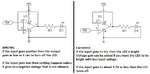
Another solution I came across is using a dual opamp like LM358N for RX/TX LED.

The schematic was posted on StackExchange:

GHauy.png

I am really interested in implementing this method. I have the parts already. I want to read the sensor data with an Arduino Uno. The sensor uses RS232. I convert it via max3232 to Arduino. I want to see the activity via LED. Unfortunately I don't have my electronic devices and parts with me at the moment to test it and I am under pressure to see whether this works or not? I have seen at least one person reported that his LEDs remained on all the time using this method. But his UART voltage levels were 1.8V. Mine is 5V. Don't know whether it is relevant or not.

Also I would like to know how to stretch the pulse of the LED very simply? Can I use a capacitor in parallel to LED? I am transferring at 100K baudrates. I don't really care too much about the blinking. I just want to know something is happening! Staying on for 0.5 ~ 1 s or blinking 0.1s are fine ( or something in between ).

I dont have LD358D LT Spice model and various op amp models are giving me strange results!!! from staying on or oscillating between 25 and 28 mA at LED. I have already knocked myself out :fight::bang: and I'd be very grateful if you amazing people at EDABOARD could reach out to me.

Sincerely,
:thumbsup::thumbsup::thumbsup:
 
Last edited by a moderator:

Hi,

first I want to tell you that you should use a comparator instead of an OPAMP.
An OPAMP is designed for negative feedback and the output is not meant to be close to the supply rails (= analog output)
A comparator is made for (large) differential input voltage, and it is meant that the output is either at the negative or positive rail (switching output)

Some OPAMPs can work like a comparator, but some don´t

***
Now to your problem:
Very important informations are:
* What signal voltage do you expect (nominal and max)? --> Is it UART TTL level or true RS232 (where you expect up to +/-15V)
* What supply voltages are available?

To your circuit..
It uses an OPAMP but the circuit is for a comparator.
I assume the supply voltage is 0V / 5V and the signals are TTL levels.

TTL levels are true low if the voltage is 0.7V or lower, and they are high when they are 2V or higher.
So with your circuit you "compare" two voltages. One is the TTL level at IN- and the other is at IN+.
If the comparator output just should be the (inverted) state of the signal lines, then you should compare them with a fixed voltage between 0.7V and 2.0V.
Here is the problem: You compare it with the output. (OUT is connected to IN+)
If the output is high (5V) then the IN- input should be higher as 5V to make the output switch.
The same is when the output is low, then you need an input voltage lower than 0V for the output to switch.

What to do:
* Disconnect OUT from IN+
* use a voltage divider (made of two resistors) to divide the supply voltage 5V to --> 1.5V
* The values should be around 1k to 30k, this is not critical. But the upper resistor should have about twice the value of the lower resistor.
* connect bot resistors in a string, the lower connection to GND, the upper connection to VCC, the center to IN+

Mind: UART signals are idle high, so your LED should be active when the signal lines are low.

****
Try this first, then when all is running we could go on and improve your circuit.

Klaus
 
Dear KlausST and other forum members.

Thank you very much for responding.

1. First of all, I must say that I want to attach LEDs to the UART TTL level. So your assumption was right.

2. I have no problem implementing this circuit with a comparator, but I am not familiar with them. Is it possible to name several of the standard single, dual and quad comparators suitable for my application? I am not ordering on the Internet and I have to buy them from electronics shops. So I would be thankful if you could name those parts that are relatively common.

3. Does comparators need feedback loop? Is the circuit similar to the OpAmp ?

4. You asked "What supply voltages are available?" there are supply voltages available between 3.3V to 9V. If you asked this to see if I can supply 1.5V to the non-inverting (In+) input or not, I was successful able to produce that voltage with the voltage divider you mentioned.

5. I used the voltage divider and it worked absolutely fine. I want to know if it is possible to drop the voltage for the (In+ non-inverting input) with a Zener diode or not? Does the Zener diode using that way need any current limiting resistor assuming that input impedance is in mega ohm range? It helps me to make the circuit on the PCB more compact.

6. I used max3232 (which is very similar to max232). The TTL level input and output behaved differently.

One of them ( I don't remember which one) was on and off (blinking very fast) with very dim light before supplying the RS232 (turning the sensor on which indicates the signal through RS232). Then when the sensor was on the rhythm of the blinking was different but still dim.

password: edaboard

The other one was off when the sensor (and RS232) was off, then when I turned the sensor on, it gave a very bright light for a second and started blinking relatively dimly. I think it was because of the high speed transfer (120kbps). The light level (even in a dark room) was not satisfactory. It is only relatively bright when you are looking at the LED from above

Video on the next post...

How can I stretch the pulses with a simple method to get a bright indication? I prefer blinking rather than an LED staying on. And I am not able to implement this with a code on my arduino... I have thought about that.

7. oh, by the way, does the opamp (or comparator) need a bypass capacitor for supply voltage??

Thank you very much in advance :thumbsup::thumbsup:
 

password: edaboard

or the second condition!
 

Hi, your videos play properly inside your post, via sharing from vimeo.com.

Your post #4 video shows the led blinking, as though it indicates irregular rapid activity.
 

The forum rules didn't permit me to include both videos in one post

First video:

The LED is blinking very fast before turning on the Sensor, without any RS232 signal. It is connected to Rx of the Sensor. When I turn on the sensor, the rhythm changes but it is still very dim.

Second video:

The other LED connected to Tx of the sensor is off when the sensor (and RS232) is off, then when I turn the sensor on, it gives a very bright light for a second and then starts blinking relatively dimly. I think it is because of the high speed transfer (120kbps). The light level (even in a dark room) is not satisfactory. It is only relatively bright when you are looking at the LED from above.
 

Hi,

Instead of using a comparator I'd use a schmitt trigger logic IC. (HC14)

* from TxD pin connect one gate just a buffer (inverting)
* at this output connect a diode (anode). Catode to a capacitor. Other capacitor pin to gnd.
* add a pulldown to the capacitor.
* Conect a second schmitt trigger to the capacitor.
* connect a LED (cathode) to the output. Series resistor to VCC.

How it works:
* when TxD is active (low), then the first gat charges fastly the capacitor
* the pulldown discharges the capacitor slowly (pulse stretching)
* the second gate output drives the LED.

Try a 10nF capacitor, a 1N4148 and a 1Mohms resistor.

Klaus
 
@KlausST

May I ask you to kindly provide a schematics?

Can I use it for the Rx also?

Is HC14 the same as 74HC14? Sorry I am very new to electronics.

Can this method stretch pulses to something like 200~300ms?

And assuming that the transmission is happening at 120kbps, is it going to stay on? or is it going to blink?!

Thank you.
 

Thank you very much.

I will implement this circuit and I will post the video...

One last question for now. Can I be sure that this circuit is not going to affect the transmission while charging the capacitor or in other ways? It is very important for me that the integrity of the other part of transmission remains intact. Does the first HC14 need power supply and ground?
 

Hi,

* HC14 is short for SN74HC14 (or similar) you could use AC, LV, LVC ... but dont use "T" like HCT...

* the same is for Rx

* stretch pulses: increase R or C or both.

* The LED is ON with the first bit transmitted. it is retriggered with every sent "0", then it stays continously ON until the delay/stretch time is over.

* for a raw estimation of time use: t = R x C
--> 10nF x 1M Ohms = 10ms (enough for the eye to recognize)

***
RxTx.jpg
This is some kind of "dirty" circuit, because the charge current to the capacitor is not externally limited.
A more clean solution is to add a series (with the diode) resistor of about 330 Ohms.

***
Rv determines the LED current. It´s value depend on supply voltage, estimated LED current and LED_forward_voltage and HC14_ouput_voltage_low. Try 470 Ohms.

Klaus

- - - Updated - - -

Hi,

in one HC14 IC there are six schmitt trigger gates. Only one GND and only one VCC.

The input of the gates is very high ohmic, so it is very unlikely that the circuit affects the function.
(Some more dirty circuits use the Tx/Rx line directely to charge the capacitor. Here one can expect problems with data transfer.
With the given circuit the first gate acts like a buffer to provide enough current to charge the capacitor quickly)
But for sure there are current pulses to charge the capacitor ... on VCC and on GND. Therefore a proper GND plane and the bypass capacitor is urgent.

Connect unused gate inputs to GND. Don´t let them float.

Klaus
 
Opamps are fine and will switch faster than your vision. Comparators and digital logic switch much faster but they are not needed.

Your opamps have positive feedback so they do not work. I show them with 100% negative feedback then the LEDs turn on brightly when the input is at Vcc level and turn off when the input is about 1.7V or less. Two resistors can add gain so that the LEDs turn on at a lower input voltage.
 

Attachments

  • LED driver.png
    LED driver.png
    17.1 KB · Views: 307
The light level (even in a dark room) is not satisfactory. It is only relatively bright when you are looking at the LED from above.

LED lenses range between diffuse and clear. Your led appears to be diffuse. A clear lens is often narrow-beam. It may help if you use a high-efficiency led, or a bright white.

If you want to experiment, try grinding or filing away the diffuse plastic lens, until a small amount remains over the PN junction. This will make the led brighter. Create a flat top, at an angle which maximizes brightness toward your viewing direction.
 
The light level (even in a dark room) is not satisfactory. It is only relatively bright when you are looking at the LED from above.
Then you are using cheap ebay LEDs that are old dim ones in a case that focusses the light into a brighter but narrow beam. Modern good quality LEDs are sensitive, bright and have a wide viewing angle.
An LED appears dimmed if its on-duration is less than 30ms and that is how some LED dimmer circuits work including rear LED lights on cars and busses.
 

Dear Friends,

Finally I was able to test this circuit. It is working very good. The LED pulses are not as good as it seems in the video. I think the refresh rate of camera is compensating for this. I wish it was as good as what it seems on this video:

**broken link removed**

At some point in the video, the LED becomes brighter. That's when I put a 470nF in parallel with the 10nF capacitor suggested in former posts.

The LED in the video is on the RX Side of the Arduino. I mean Arduino Mega 2560 pin number 19 which is RX1! The TX one is extremely dim (It is not in the video). I think a much much bigger capacitor is needed to make it visible.

I am deeply grateful for all of the guidance, especially from user KlausST.

Now I have several questions:

1. Can I use 1N5408 instead of 1N4148? I want to use beefy components on my PCB.

2. Is it enough to connect all of the unused components to the gnd plane? Do I have to care about unused outputs of 74HC14?

3. Is it possible to kindly provide a similar circuit for the RS232 side (with schematics?)? I am not sure about the voltage levels!! But I think it should be around +/- 13V. The TTL LED is working so well that I want to use something similar on the RS232 side. Also I think maybe other people will find it helpful in the future.

I am deeply grateful!! ;-)
 
Last edited by a moderator:

Hi,

Please show us your actual circuit...with values and the names of parts you used...
****
1) the 1n5408 should work also.
2) only inputs... to gnd plane. Don't care about the outputs.
3) you need a power supply to drive the LEDs, but usually you don't have on the RS232 lines. I don't like the idea, because it may influence the RS232 communication.

Klaus
 

Thank you very much KlausST.

I'd be thankful if you could:

1. add to my last post, under the video: " password: edaboard "

2. add [SOLVED] to the thread name.

3. change the thread name to a more relevant one if you think it is a good idea.

Once again I am thanking EDABOARD members, especially user KlausST.

Sincerely,
 

Hi,

* HC14 is short for SN74HC14 (or similar) you could use AC, LV, LVC ... but dont use "T" like HCT...

* the same is for Rx

* stretch pulses: increase R or C or both.

* The LED is ON with the first bit transmitted. it is retriggered with every sent "0", then it stays continously ON until the delay/stretch time is over.

* for a raw estimation of time use: t = R x C
--> 10nF x 1M Ohms = 10ms (enough for the eye to recognize)

***
View attachment 126373

This is some kind of "dirty" circuit, because the charge current to the capacitor is not externally limited.
A more clean solution is to add a series (with the diode) resistor of about 330 Ohms.


***
Rv determines the LED current. It´s value depend on supply voltage, estimated LED current and LED_forward_voltage and HC14_ouput_voltage_low. Try 470 Ohms.

Klaus

- - - Updated - - -

Hi,

in one HC14 IC there are six schmitt trigger gates. Only one GND and only one VCC.

The input of the gates is very high ohmic, so it is very unlikely that the circuit affects the function.
(Some more dirty circuits use the Tx/Rx line directely to charge the capacitor. Here one can expect problems with data transfer.
With the given circuit the first gate acts like a buffer to provide enough current to charge the capacitor quickly)
But for sure there are current pulses to charge the capacitor ... on VCC and on GND. Therefore a proper GND plane and the bypass capacitor is urgent.

Connect unused gate inputs to GND. Don´t let them float.

Klaus


Dear Klaus and others,

As you know from my "MAX232/MAX3232 Heating Up" top, I am finalizing my circuit on a PCB. I am almost finished with this "RX/TX LED indicator with pulse stretching". Now I have one concern, so I thought I should check with you guys.

Datasheet says:

MaxRating74HC14.jpg

I am using two inputs for the RX LED and the other two inputs for the TX LED.

In the quoted part of this post, you have mentioned that it is a good idea to include a 330 ohm resistor. Ok. It means that track can only supply up to 15milli ampere. I believe since I am using two pairs for RX and TX it is about 30milli ampere. Forgetting about the duty cycle, and assuming the worse case scenario, Do you still suggest 330 ohm resistor? ( I am using baudrates between 9600 to 120K )

I am baffled about Iik, Iok, Io... Icc and Ignd are fine. But I don't know the relationship between Iik, Iok, IO to the current that is passing through the resistor behind the 4148 diode. Also my leds are rated between 15 and 20 ma! I don't know whether there is a significance between the current that is passing through the LEDs and these Iik, Iok and Io...

Oh, and do you also suggest that I use a 100ohm resistor in series with 74HC14's Vcc to limit the maximum current to preclude any possibility of excessive current consumption!?

I know that most probably this circuit will last for ever. But I really want to understand the math.

I am very deeply grateful :thumbsup:
Sincerely,
 

Hi,

Relax.
None of the limits will be a problem.
All named "DC" relate to continous current. But you don't have continous current.
All named "diode" relate to the internal (ESD) protection diodes. But the diodes will not be activated.

You say you use "pairs": Don't parallel two inverters with that kind if "analog" input voltage. Each gate will have a slighteky different threshold voltage, if now one gate recognizes the input voltage as "high" and the other as "low", then the connected outputs fight against each other. Short circuit current..

And..don't use a current limiting resistor in the VCC (nor GND) line.

LED current. I rather use high efficiency LEDs with low current than standard LEDs with high current. Use max. 15mA per LED.

Klaus
 
Status
Not open for further replies.

Similar threads

Part and Inventory Search

Welcome to EDABoard.com

Sponsor

Back
Top