Continue to Site

Welcome to EDAboard.com

Welcome to our site! EDAboard.com is an international Electronics Discussion Forum focused on EDA software, circuits, schematics, books, theory, papers, asic, pld, 8051, DSP, Network, RF, Analog Design, PCB, Service Manuals... and a whole lot more! To participate you need to register. Registration is free. Click here to register now.

Power Supply with an output of 12V using Silicon Controlled Rectifier?

Status
Not open for further replies.

DiegoSilang

Newbie level 4
Joined
Jan 16, 2016
Messages
5
Helped
0
Reputation
0
Reaction score
0
Trophy points
1
Activity points
40
Power supply 12V using SCR.JPG
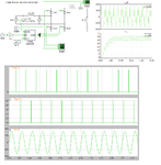
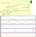
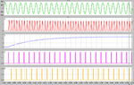
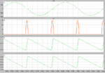
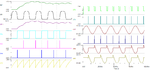
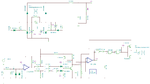
Hello. I'm trying to resolve this circuit simulation by means of Multisim. Is there any problem with the connections? Somehow the fuse always breaks. I'm trying to get an output of 12V using scr + 4n25 optocoupler. Also, I'm trying to construct an actual circuit using this simulation. Any help would be much appreciated.
 

You must be firing the SCR's in the wrong combination or sequence. Look below at the required sequence for it to work properly.
 

Attachments

  • SCR_rect.png
    SCR_rect.png
    74 KB · Views: 142

scr bridge.JPG
Thank you for replying. Please kindly elaborate what sequence your trying to explain? Which components are not in the right order? Much appreciated.
 

Hello, thank you for replying. May I ask for your assistance? I'm having trouble what sequence you're trying to explain. Can you please elaborate further if it's not too much trouble. Thank you very much

It is possible to fire a wrong combination that will put a short circuit over the incoming supply.
 

The 0.24ohm resistor is the assumed load.
 

This 0.24 Ohm will cause a very heavy current to flow. Do the math.

From your circuit, it appears you are firing all the SCR's in the bridge at the same time. This will cause a dead short.
 

I presume the output of the trigger is correct. I just copied the circuit diagram with little knowledge of it thinking it would produce a 12V output from AC to DC. Can you help me resolve the directions of the wrongly positioned SCRs?

Can you give me specific changes that I must do in order to get a 12V dc output? Much appreciated
 

Look at the firing angle needed in the diagram below to get about 12V output. This is with C1(10000 uF).
 

Attachments

  • 12V_out.png
    12V_out.png
    90.6 KB · Views: 132
  • 12V_out1.png
    12V_out1.png
    105.7 KB · Views: 115

It is important to note that with no DC choke very high peak currents will result. Compare previous post and this below with no DC choke.
 

Attachments

  • 12V_out1_noL.png
    12V_out1_noL.png
    40 KB · Views: 117
Hello, may I clarify kindly that you're implying the scr bridge rectifier is totally wrong?
 

The implication is that to get 12V output you need to trigger the SCRs in the correct sequence and at a very precise time just before zero crossing occurs. As you will only get a brief 'pulses' of power with relatively long gap between them, the charging current to the capacitor (C4) and current into the load will be extremely high. Your load resistor suggests about 50A load is expected, adding the charging curent to get anything like a clean output would easily double that to 100A and might be considerably more.

Not only does your schematic trigger all SCRs simultaneously, which you have already be warned will short the incoming power, but you also wire the LED sides of all the optocouplers in parallel which is a bad idea. Use a current limiting resistor in series with each LED. You also have no feedback mechanism to regulate the voltage, you will almost certainly find it's output is unstable under different input voltage, load and temperature conditions. The input voltage to U1A also exceeds it's common mode rating by about 50% !

SCR regulated supplies are better suited to high current power supplies where the output voltage is close to the input voltage so the SCR is conductive over a larger part of the AC half cycle. Often they are used as a pre-regulator and followed by a more precise regulator to give stable output.

Brian.
 

For an SCR bridge rectifier, only two SCRs are required, the other two can (should?) be replaced with ordinary diodes. This simplifies the firing circuit. With 230 V @ 1A in -230W, you can not get 12V@ 50A out (600W).
Frank
 

For an SCR bridge rectifier, only two SCRs are required.
And there's absolutely no risk to cause a bridge short. At worst case, the SCRs act like ordinary diodes. By nature of the rectifier bridge, only one of the two SCRs (or 2 out of 4 in the original circuit) can conduct. Thus there's nothing against using a common trigger generator for both polarities, operated with 100 Hz repetition frequency.

The optocoupler trigger circuit must be supplemented with rectifiers diodes, opto transistors don't have more than 5 or 7 V reverse blocking. Unless you have sensitive SCRs, opto transistors aren't capable of driving the required trigger current. If the circuit is intended as prototype of a real circuit, you would use a different trigger device.
 

I think it is easier to use trigger transformers than opto's. Below is a simulation and wave-forms of such a bridge with an average output at 12 V and 1A.
 

Attachments

  • phase_rect.png
    phase_rect.png
    64.1 KB · Views: 116
  • phase_rect1.png
    phase_rect1.png
    53.4 KB · Views: 128

Status
Not open for further replies.

Part and Inventory Search

Welcome to EDABoard.com

Sponsor

Back
Top