Continue to Site

Welcome to EDAboard.com

Welcome to our site! EDAboard.com is an international Electronics Discussion Forum focused on EDA software, circuits, schematics, books, theory, papers, asic, pld, 8051, DSP, Network, RF, Analog Design, PCB, Service Manuals... and a whole lot more! To participate you need to register. Registration is free. Click here to register now.

[SOLVED] BJT buck converter getting hot

Status
Not open for further replies.
R

red_alert

Guest
I was experimenting a BJT buck converter using a SG3525 in a pretty uncommon configuration (PWM pulses through the VC terminal, outputs connected to the ground).

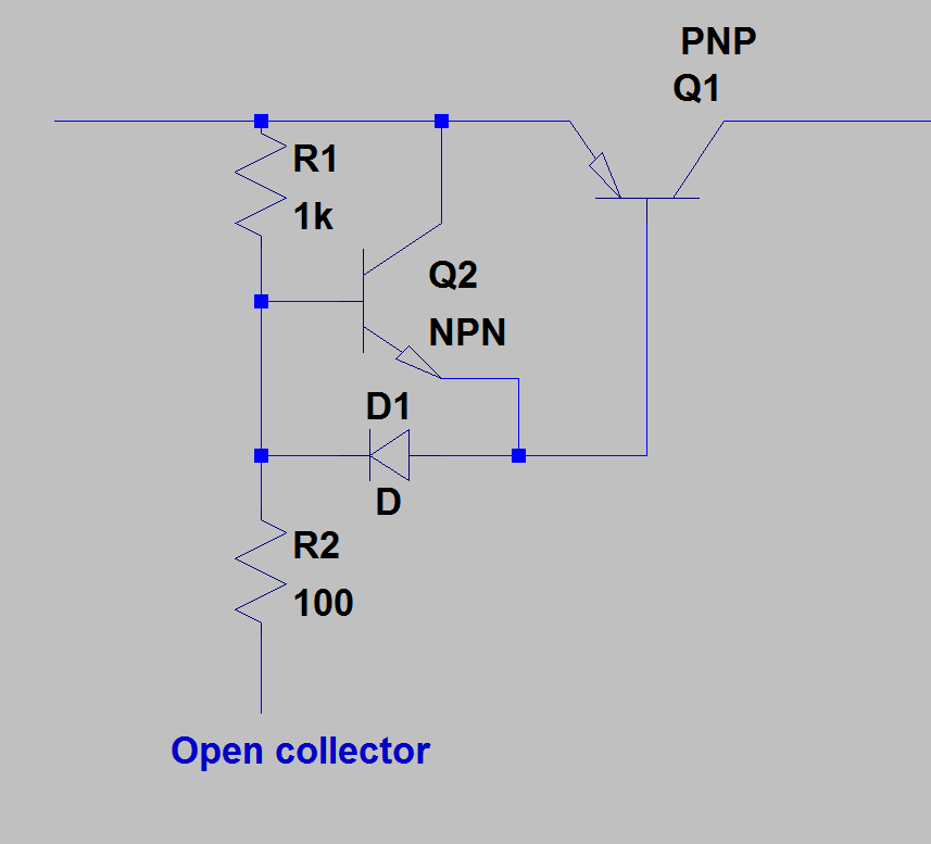
The schematic diagram is as follow:

buck-bjt.gif

The input voltage is 24V, the output voltage is 12V, the intended load current is 10A and the switching frequency is 25kHz. The BJT is a high power/high frequency PNP transistor.

Overall, the circuit actually works.. but as the output current increases over 1-2A, the BJT is getting really hot.

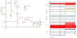
I checked the waveforms for the base signal and the rise/fall times are quite big. As the rise time could be shortened by a higher base current (I'm going to put another BJT in a darlington configuration), I have no clue on how to speed up the turn off process.

Looking at the diagram, the only path for removing the saturation charge is the B-E resistor (R1). That's because the SG3525 output (VC) is an open collector and it's actually floating in off state.

I even tried a schottky diode across base and collector to limit the reverse C-B diode polarisation (saturation mode) to a smaller value (schottky forward voltage) thus the BJT it's not going into a deep saturation.

Neverthless, the waveforms wasn't changed too much and the heat is still present.

I'm thinking of an additional circuit - to put a small BJT across the B-E of the main (power) BJT and force it into the saturation mode when the PWM signal is floating.

Does anyone have any other ideas on how to deal with this situation?
 

I've attached a simple circuit to speed up the turn-off of the BJT. Q1 is driven on through R2, and when you want to switch it off fast, Q2 will assist with that. D1 should be a high speed schottky. You should use a mosfet instead of a BJT though. The same basic driver circuit will work with a P channel FET.


    V

    Points: 2
    Helpful Answer Positive Rating
It happened to only have a BJT available (and n-FETs though) so I thought it was a right time to experiment (I've never used BJT switches before).

Thanks for your suggestion, that's a very clever idea. I'll make the changes and I'll post back the results.
 

If I look at the SG3525 output circuit (datasheet figure 9), I don't believe that the said "uncommon configuration" is a good idea. Instead you'll better use an additional NPN driver transistor to perform the level translation.

Darlington configurations may be necessary if the required base is current is too large to be handled by the level translator. Achieving fast switching though isn't easy.

I must confess that I stopped designing bipolar switchers about 20 years ago.
 

    V

    Points: 2
    Helpful Answer Positive Rating
I guess I need some kind of totem pole configuration too, to force both turn on and turn off procedures.

Nevermind, I'll give a shot to @mtwieg suggestion and if there's no improvements I'll put a MOSFET half bridge in place (like you said, it's 21st century outside).
 

It's surely possibly to design BJT switchers with good efficiency. My ultimate design e.g. used a current feedback transformer to generate the base control power. But it's still easily outperformed by a MOSFET switch.
 

I've designed a simple circuit to force turn-on/turn-off of the main BJT.

buck-bjt-new.gif

I have to remind that the driving PWM signal comes from the VS pin of SG3525 (open collector).

Thus while the input (PWM) is LOW, the additional BJT is saturated, helping to fast turn-off the main BJT.

While the input is HIGH (actually, open), the main BJT is saturated through R3 resistor.

Is there any hidden problem with the circuit? I'm going to test it anyway but I'm not at home right now.
 

Are you intentionally inverting SG3525 output polarity?

Base current is rather low, you'll either use a darlington (high saturation voltage, slow switching) or output current is respectively low.
 

I took the SG3525 output (VS) "as is" - the duty cycle will adapt to this situation.

And yes, I realized the base current is a little too low. I could decrease the base resistor though but I want to minimize the losses.

Actually, I'm already using a darlington configuration in my implementation. Speaking of that, do you think I should double the auxiliary circuit to fast turn-off each of the darlington BJT?.. or should I turn-off just the main BJT?.. or the whole darlington configuration at once?
 

The input voltage is 24V, the output voltage is 12V, the intended load current is 10A and the switching frequency is 25kHz. The BJT is a high power/high frequency PNP transistor.

That is a lot of current. Maybe you could give some component values (switching transistor and diode) for us to better evaluate the design.
 

It's a 120W rated DC-DC converter thus I wouldn't call it "a lot of power" (the maximum load it's about 60W though).

Anyway, I'm using an "audio grade" PNP transistor (15A/230V/30MHz: 2STA1962) and a ultrafast recovery diode (15A/200V/20ns: STTH1502).
 
Last edited:

I took the SG3525 output (VS) "as is" - the duty cycle will adapt to this situation.
The control signal inversion point is referring to your latest circuit in post #7, not the original one. Of course the controller can't simply "adapt" to an inversion.

Regarding suitable output current, review the current gain and output charcteristic diagrams in the datasheet. 10 A output current would require base currents of 0.5 to 1A (forced current gain of 20 down to 10). That's hardly possible without a darlington configuration.
 

    V

    Points: 2
    Helpful Answer Positive Rating
Well, I guess it's not worth experimenting with BJT switches anymore.

In the mean time, I struggled to design a similar circuit for driving a MOSFET (n-FET, high-side). The circuit looks like that:

bjt_driver.gif

I've tried to limit the (floating) gate signal using a zenner diode (D1, 12V). I've put an antiparallel (D2) diode too, for better recovery characteristics.

Here come my doubts:

1. Do I have to put a resistor between MOSFET source and ground, for biasing those diodes (or is the current path through load/D3 enough)?

2. R4 value is just a guess; do I need to use separate values for turn-on/turn-off?

Any other suggestions for improvements are welcome.
 

In the mean time, I struggled to design a similar circuit for driving a MOSFET (n-FET, high-side). The circuit looks like that:

View attachment 114406

Not a good idea. To turn the NMOS transistor fully on, the gate voltage must swing 10 or 12 V above the supply input voltage which isn't possible with your circuit. Needs some kind of bootstrap supply or a DC/DC converter.
 

    V

    Points: 2
    Helpful Answer Positive Rating
Oh, stupid me! I was under BJT influence (the circuit was derived from that one). Seems like I'm running in circle.. I came to the same conclusion: I need a half bridge (synchronous) design. Thank you very much for your help.
 

If your application is not that critical as far as output ripple and regulation, then this circuit may work for you. It uses a P-chan MOSFET and is self-regulating. I have not tested the design at 10A, but it works well up to a few amps. With the proper MOSFET and switching diode selected, it looks like it may handle 10A with near 90% efficiency. At 2A, I could get near 93% efficiency. At this current level you may also need a small damping resistor like 22R in series with the gate of the MOSFET.

This circuit is my variation of the "roman-black" buck BJT regulator.
 

Attachments

  • 10A_buck.png
    10A_buck.png
    58.8 KB · Views: 266
Last edited:
Actual prototype.
 

Attachments

  • Buck_proto.jpg
    Buck_proto.jpg
    324.5 KB · Views: 172

I also stopped using bipolar for switching circuits a couple of decades ago.

In addition to what has been mentioned, driving them into saturation (required for good efficency) significantly increases its turnoff time.

And, before I forget.............bipolars have secondary breakdown issues. Google "safe operating area"
 

Status
Not open for further replies.

Similar threads

Part and Inventory Search

Welcome to EDABoard.com

Sponsor

Back
Top