Continue to Site

Welcome to EDAboard.com

Welcome to our site! EDAboard.com is an international Electronics Discussion Forum focused on EDA software, circuits, schematics, books, theory, papers, asic, pld, 8051, DSP, Network, RF, Analog Design, PCB, Service Manuals... and a whole lot more! To participate you need to register. Registration is free. Click here to register now.

[PIC] How to interface EM-18 RFID reader with PIC16f628A using MikroC pro

Status
Not open for further replies.

Mrunal Ahirrao

Full Member level 2
Joined
Nov 26, 2012
Messages
133
Helped
2
Reputation
4
Reaction score
2
Trophy points
1,298
Location
India
Activity points
2,213
Hi all,
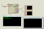
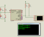
I am trying to interface RFID reader with PIC16F628A using UART but it doesn't work. I tried using MikroC libraries but failed, so I tried by manual declaring all registers associated with USART. But it again failed. Any help would be appreciated.

Code:
sbit LED at RB3_bit;
unsigned char rdata[12];
unsigned char idata[]="84008159124E";
unsigned short i;

void interrupt()
{
 if(PIR1.RCIF==1)
 {
  rdata[i]=RCREG;
  i++;
  }
}


void main()
{
CMCON = 7; // Disable Comparators
TRISB = 0b00000110;
SPBRG=25;		// Fill SPBRG register to set the baud rate
RCSTA.SPEN=1;			// To activate serial port (Tx and Rx pins)
RCSTA.CREN=1;			// To enable continuous reception
PIE1.RCIE=1;			// To enable the Reception (Rx) Interrupt
INTCON.GIE=1;
INTCON.PEIE=1;
TXSTA.BRGH=1;
TXSTA.SYNC=0;


do{
if(rdata==idata)
{
LED=1;
}
}while(1);
}

The LED should lit but it doesn't!
 

EM -18 RFID Cards work on 12 byte data transfer
And first you check a basic code of sending and receiving it to PC via UART using Mikeo C ,
so that it's assured that there is some problem after that we'll discuss on RFID Interfacing
 

EM -18 RFID Cards work on 12 byte data transfer
And first you check a basic code of sending and receiving it to PC via UART using Mikeo C ,
so that it's assured that there is some problem after that we'll discuss on RFID Interfacing

yes the same idea I followed to first check my UART communication. But it failed!
here is the code:
Code:
void main() {
unsigned char MyError, Temp;
CMCON = 7; // Disable Comparators
TRISB = 0b00000010;
UART1_Init(9600);
Delay_ms(100);
UART1_Write_Text("Testing UART! ");
newline();
do {
UART1_Write_Text("Type in a Number: ");
while(!UART1_Data_Ready());
Temp = UART1_Read();
newline();
UART1_Write_Text("You entered: ");
UART1_Write(Temp);
newline();
} while(1); } // End main()

This code is correct. I have copied this code from link:https://embedded-lab.com/blog/?p=1296

but this code shows nothing on terminal!
 

Any other Code you tried like LED blinking and all other using Mikro C like i wanted to know that whether the hex file are created Actually i am thinking other side that whether MikroC is working or not,

or else do one thing there is a library in Mplab_IDE
You can use that also first check that thing also

Meanwhile also define newline() function in your code
 

Try this code for testing UART.

Fosc = 4 MHz and baudrate = 9600 bps


Code C - [expand]
1
2
3
4
5
6
7
8
9
10
11
12
13
14
15
16
17
18
19
20
21
22
23
24
25
26
27
28
29
30
31
32
33
void newline(){
    UART1_Write(0x0D);
    UART1_Write(0x0A);
}
 
void main(){
 
     unsigned char MyError, number[24], i;
     CMCON = 7; // Disable Comparators
     
     TRISA = 0xFF;
     PORTA = 0x00;
     TRISB = 0x02;
     PORTB = 0x00;
 
     UART1_Init(9600);
     Delay_ms(100);
 
     UART1_Write_Text("Testing UART!");
     newline();
 
     while(1){
       UART1_Write_Text("Type in a Number: ");
       while(!UART1_Data_Ready());
       while(number[i] != 0x0D)
            number[i++] = UART1_Read();
       number[i] = '\0';
       newline();
       UART1_Write_Text("You entered: ");
       UART1_Write_Text(number);
       newline();
     }
}


Attachments

  • UART PIC16F628A.rar
    29.1 KB · Views: 111
Last edited:

Any other Code you tried like LED blinking and all other using Mikro C like i wanted to know that whether the hex file are created Actually i am thinking other side that whether MikroC is working or not,

or else do one thing there is a library in Mplab_IDE
You can use that also first check that thing also

Meanwhile also define newline() function in your code

I have successfully completed many parallel communications projects and it works well! So no problem of MikroC.

- - - Updated - - -

Thanks jayanth.devarayanadurga I will try this code and tell you about it.
 

Try this code for testing UART.

Fosc = 4 MHz and baudrate = 9600 bps


Code C - [expand]
1
2
3
4
5
6
7
8
9
10
11
12
13
14
15
16
17
18
19
20
21
22
23
24
25
26
27
28
29
30
31
32
33
void newline(){
    UART1_Write(0x0D);
    UART1_Write(0x0A);
}
 
void main(){
 
     unsigned char MyError, number[24], i;
     CMCON = 7; // Disable Comparators
     
     TRISA = 0xFF;
     PORTA = 0x00;
     TRISB = 0x02;
     PORTB = 0x00;
 
     UART1_Init(9600);
     Delay_ms(100);
 
     UART1_Write_Text("Testing UART!");
     newline();
 
     while(1){
       UART1_Write_Text("Type in a Number: ");
       while(!UART1_Data_Ready());
       while(number[i] != 0x0D)
            number[i++] = UART1_Read();
       number[i] = '\0';
       newline();
       UART1_Write_Text("You entered: ");
       UART1_Write_Text(number);
       newline();
     }
}

Thanks for the code. But nothing is displayed on PC.
 

The last character should be 0x0D else it will not come out of UART read loop. Use below code. It reads 12 characters.


Code C - [expand]
1
2
3
while(i < 12)
            number[i++] = UART1_Read();
       number[i] = '\0';


The last character should be 0x0D else it will not come out of UART read loop. Use below code. It reads 12 characters.


Code C - [expand]
1
2
3
while(i < 12)
            number[i++] = UART1_Read();
       number[i] = '\0';


But it didn't even displayed the "Testing UART" line or "Enter number".
 

Just use a simple for loop
it might help you as EM-18 module ID- cards are of 12 bytes
so apply the following loop
Code:
unsigned char i,unsigned char card[12];
for(i=0;i<12;i++)
{
card[i] = Receive Function for UART();             // receive card value byte by byte ;;12 Byte
}
Try this
 

It works fine for me. Check your hardware.

99213d1385743695-rfid.png


99216d1385744673-rfid2.png
 

Attachments

  • rfid.png
    rfid.png
    41.6 KB · Views: 178
  • UART PIC16F628A rev1.rar
    65.4 KB · Views: 98
  • UART PIC16F628A rev2.rar
    99.2 KB · Views: 113
  • rfid2.png
    rfid2.png
    37.1 KB · Views: 129
Last edited:
It works fine for me. Check your hardware.

99213d1385743695-rfid.png


99216d1385744673-rfid2.png

thanks. Your code is very robust I will try it and tell you.In second image why 10K resistors are used?

- - - Updated - - -

Just use a simple for loop
it might help you as EM-18 module ID- cards are of 12 bytes
so apply the following loop
Code:
unsigned char i,unsigned char card[12];
for(i=0;i<12;i++)
{
card[i] = Receive Function for UART();             // receive card value byte by byte ;;12 Byte
}
Try this

thanks. I will try it
 

hi again! Now its showing "testing UART" "Type in number" but I am not getting Echo back!
 

On hardware. And I have found the problem.There is no stop bit sent from PIC to PC and from PC to PIC! and when I pull the receiving lines high then again the RB1/RX of PIC is gone high and PIC ready to receive from PC or else If i dont pull then it would never respond to data from PC! and same with PC. When I pull high the transmit of MAX232 then it stops transmitting data to PC and it will now respond to data from PC.
 

Its working now I replaced max232, and its working correctly. Now I am successful in UART communication! Now I will try to interface RFID reader with PIC16F628A. Thanx all of u!
 

Status
Not open for further replies.

Part and Inventory Search

Welcome to EDABoard.com

Sponsor

Back
Top